jwb said:I don't get particularly good results from ostripper's latest simulation, either. Mostly because the naive input and VAS contribute a huge amount of distortion before the output stage even comes into play.
People need to take a whole-system approach to implementing this thing. There's no point in ruining a perfectly good output stage with a passively-loaded input stage. Try an active (current mirror) load.
I also get better simulator results with paralleled devices in the output.
Right, I agree
Cheers
Stinius
jwb said:I don't get particularly good results from ostripper's latest simulation, either. Mostly because the naive input and VAS contribute a huge amount of distortion before the output stage even comes into play.
People need to take a whole-system approach to implementing this thing. There's no point in ruining a perfectly good output stage with a passively-loaded input stage. Try an active (current mirror) load.
I also get better simulator results with paralleled devices in the output.
That was just the output stage, I just wanted to get calibrated. Right now I still stick with Charles Hansen's comments, that it's a nice trick to bias the input followers independently from the output transistors bias current.
try simulating your ideal input stage (VGS) and read off the distortion and stability results with it's feedback looped around itself.jwb said:I don't get particularly good results ..........because the........input and VAS contribute a huge amount of distortion
There's no point in ruining a perfectly good output stage
Then add on the KRILL output stage and read off the distortion and stability results.
Are the two schemes different?
Where?
How much?
Tell us how good KRILL is/isn't.
By jwb - I don't get particularly good results from ostripper's latest simulation, either. Mostly because the naive input and VAS contribute a huge amount of distortion before the output stage even comes into play.
That's not my input/VAS... the krill OPS can do (attached)
KILLER specs (for those who like these things 😀 ) with
balanced or CM based alternatives. Krill ROCKS, adding
only .0015% to the total at 20K.. about the same as
the leach triple EF. I did do both with global NFB..but only
to be fair. But ,for a hobbyist ,what steve posted will sound good,
(my self amp can only do .05% at 20k
 ) I listen to
it daily and .. no complaints)
Ps.. edit. I forgot to add a DC blocking cap to krill1.asc.. sorry
(steves input/VAS seems to be in line with a typical self stage)
OS
Attachments
scott wurcer said:Steve - I'm sorry you took what I thought was a simple conversational comment as an insult or critcism. In post No. 2 you show a device with an operating Vce of (I think it was) 196mV. Someone designing "by the book" might not be comfortable with this, I personally don't care.
Scott,
I snipped most of that because I am only addressing the first paragraph.
I didn't mean to sound harsh. I didn't take what you said as a criticism or insult. I have had a bad week even by my standards. Sometimes being in great pain causes me to overreact a bit. The drugs cloud my judgment even more.
I am not trying to avoid discussing my design with you. I'm certain there is a great deal I can learn from you.
You are correct about that voltage drop. I don't remember the exact number, but that sounds pretty close. Apparently some people that design "by the book" are uncomfortable with that based on reaction here. That circuit is different from what they are used to seeing. I was looking for a way to reduce some types of distortion and this is what I came up with. I didn't plan for it to run open loop in the beginning. After testing and getting very good results, I decided to see what the distortion looked like without the output stage in the feedback loop. It still tested very good. Next, I listened to the amp configured each way. I preferred the sound without the output stage in the loop. If I had done it by the book, this circuit would not exist.
I doubt I have explained what you have been asking. What is it you want to know about this circuit that you feel I haven't disclosed?
CraigBuckingham said:
Steve, you keep putting your words in my mouth.
You say "doesn't anyone read the thread" but you do not read or maybe understand what I said in my replies. I think US and Australian English are pretty close.
I didn't claim that you claimed no improvement could be made.
I am not asking you to change anything.
I have learnt a lot from coming here but not about amplifier design.
I am not asking you to change anything in your design. I don't "think" - I know. That is why I said it.
If you said at the start of this thread or during it that you would not accept any opinions on the circuit design and that the thread was only for DIY kits and discussion about that then I would not have contributed.
I take it that is now your position so I will respect that.
You seem to feel there is nothing you can learn here about amplifier design. I will have to take your word for that. I have no idea what your line of work or education is, so I will not attempt to comment on the depth of your knowledge.
Would you mind posting a link to some of your designs so that I may be enlightened?
Steve Dunlap said:scott wurcer said:Steve - I'm sorry you took what I thought was a simple conversational comment as an insult or critcism. In post No. 2 you show a device with an operating Vce of (I think it was) 196mV. Someone designing "by the book" might not be comfortable with this, I personally don't care.
Scott,
I snipped most of that because I am only addressing the first paragraph.
I understand, no problem. I actually have avoided any comments, until I assemble a set of models and circuit that does something really interesting. A null that moves with power and frequency acts more like a fortuitous artifact on top of expected behavior.
jwb said:I don't get particularly good results from ostripper's latest simulation, either. Mostly because the naive input and VAS contribute a huge amount of distortion before the output stage even comes into play.
People need to take a whole-system approach to implementing this thing. There's no point in ruining a perfectly good output stage with a passively-loaded input stage. Try an active (current mirror) load.
I also get better simulator results with paralleled devices in the output.
The naive input here is coming from people that run a simulation and accept the results as absolute fact. I do simulations. If I run a simulation that does not correlate with measured results I re examine the simulation. I don't throw out a working design.
I have tested the whole circuit many times. The 100W production units all ran at or below 0.01% THD at rated power at 8 ohms. They didn't seem to care what your simulator said.
That passive loading of the input stage is the feedback resistor. That stage has a bandwidth over 1 MHz. That is measured as well as in simulation. Overall bandwidth is set by R1 and C1.
Use as many output pair as you want. They are cheap in simulation and don't require heat sinking.

ostripper said:
That's not my input/VAS... the krill OPS can do (attached)
KILLER specs (for those who like these things 😀 ) with
balanced or CM based alternatives. Krill ROCKS, adding
only .0015% to the total at 20K.. about the same as
the leach triple EF. I did do both with global NFB..but only
to be fair. But ,for a hobbyist ,what steve posted will sound good,
(my self amp can only do .05% at 20k
it daily and .. no complaints)
Ps.. edit. I forgot to add a DC blocking cap to krill1.asc.. sorry
(steves input/VAS seems to be in line with a typical self stage)
OS
Hi ostripper,
I have a question about your .asc files. Earlier, I could open them and look at what you had posted. Now when I try to open one it opens one of me CAD programs and tries to come up as a 3D drawing. The results are not good. What program do you generate the files with and what program do I need to use to open them? I may have to disable that naughty CAD program.
.asc files files on mine are associated (open)with "SCAD3.exe"
(known as LT 4)
http://www.linear.com/designtools/software/ltspice.jsp
Some other 3rd party software(s) might associate to a .asc
file. best case when/if you install LT4 it will "takeover"
the .asc association. worst case you will have to go
to START/SETTINGS/CONTROL PANEL and open "folder options",
find .asc in "file types" and manually associate it with scad3.exe.
in the rare case .asc will "stupify" windows and say ?????
"what do you want to do " or "open with"??
🙄
just click "open with" not "search web for solution/program'",
find lt4 (scad3) and viola..
Also , you might have to go to the CAD software / settings
or configuration and disassociate .asc from IT.
OS
Steve Dunlap said:
You seem to feel there is nothing you can learn here about amplifier design. I will have to take your word for that. I have no idea what your line of work or education is, so I will not attempt to comment on the depth of your knowledge.
Would you mind posting a link to some of your designs so that I may be enlightened?
Steve, there a some here which I hold in awe for their work and reputation. I am not saying I cannot learn anything. I spoke in past tense. I am unsure of what future posts will reveal, unfortunately, - that would be a great trick.
None of my own research work and findings, circuits etc. are available on the internet (or anywhere else). I am not as noble or unselfish as you to share my work. Most of it is not unique but more of understanding what works. Again a very subjective area.
My hat comes of to you for providing DIYers with something better than you can buy from the majority of stuff out there in its range.
The lack of loop feedback around the output stage I prefer myself. A triple (effectively) for the output stage as other(s) have mentioned previously is better than a double in my opinion also.
OK.. we have to put this to rest..
I got the same .12% on the krillOPS.asc using a virtual source.
that seems to be the problem (as I told GK) virtual zero
impedance does not give a fair/objective representation.
With the DC blocking cap put into Krill1.asc(sorry again) I got .052% at 20k.
I then disconnected the OPS and used andy's gen
on just the krill input stage , again .05%
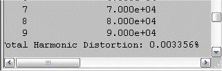
Then (I didnt include it) I built my holman input stage onto
the krillops.asc, thats where I got the .003XX from
my input stage does not seem to like the local NFB loop
coming from it's vas (but only when hooked to the krill OPS )😕
so I "wrapped" the NFB around the whole
thing (just like my triple EF) and did a strait A/B
came out to be .003% total (my holman stage .001/Krill OPS .002)
same as krill1.asc.
I only included krill ops.asc for some to "add thier own" input.
I offered these .asc's because they are stable with no
SW ringing (I had oscillation problems early on)
I noticed steves use of outputs as drivers in
the 50 watt version.. this would not be a problem, as
the crazy gain of my darlington pairs was the cause of
the instability .(hence the 1k resistors)
Also with the MJE devices as drivers, I do not trust the simulation
results, as the models are substandard.
OS
OS
I got the same .12% on the krillOPS.asc using a virtual source.
that seems to be the problem (as I told GK) virtual zero
impedance does not give a fair/objective representation.
With the DC blocking cap put into Krill1.asc(sorry again) I got .052% at 20k.
I then disconnected the OPS and used andy's gen
on just the krill input stage , again .05%
Then (I didnt include it) I built my holman input stage onto
the krillops.asc, thats where I got the .003XX from
my input stage does not seem to like the local NFB loop
coming from it's vas (but only when hooked to the krill OPS )😕
so I "wrapped" the NFB around the whole
thing (just like my triple EF) and did a strait A/B
came out to be .003% total (my holman stage .001/Krill OPS .002)
same as krill1.asc.
I only included krill ops.asc for some to "add thier own" input.
I offered these .asc's because they are stable with no
SW ringing (I had oscillation problems early on)
I noticed steves use of outputs as drivers in
the 50 watt version.. this would not be a problem, as
the crazy gain of my darlington pairs was the cause of
the instability .(hence the 1k resistors)
Also with the MJE devices as drivers, I do not trust the simulation
results, as the models are substandard.
OS
OS
ostripper said:.asc files files on mine are associated (open)with "SCAD3.exe"
(known as LT 4)
http://www.linear.com/designtools/software/ltspice.jsp
Some other 3rd party software(s) might associate to a .asc
file. best case when/if you install LT4 it will "takeover"
the .asc association. worst case you will have to go
to START/SETTINGS/CONTROL PANEL and open "folder options",
find .asc in "file types" and manually associate it with scad3.exe.
in the rare case .asc will "stupify" windows and say ?????
"what do you want to do " or "open with"??
🙄
just click "open with" not "search web for solution/program'",
find lt4 (scad3) and viola..
Also , you might have to go to the CAD software / settings
or configuration and disassociate .asc from IT.
OS
That is interesting. I have LT4 on my computer and the files in it open OK. I will try starting LT4 before I open your files. I knew about the "open folders" option but I wanted to set the correct program.
Thanks
CraigBuckingham said:
Steve, there a some here which I hold in awe for their work and reputation. I am not saying I cannot learn anything. I spoke in past tense. I am unsure of what future posts will reveal, unfortunately, - that would be a great trick.
None of my own research work and findings, circuits etc. are available on the internet (or anywhere else). I am not as noble or unselfish as you to share my work. Most of it is not unique but more of understanding what works. Again a very subjective area.
My hat comes of to you for providing DIYers with something better than you can buy from the majority of stuff out there in its range.
The lack of loop feedback around the output stage I prefer myself. A triple (effectively) for the output stage as other(s) have mentioned previously is better than a double in my opinion also.
OK I can be a little aggressive at times. Let's start over. Do you have questions?
KLe said:Steve, have you made any component changes to the 100watt version?
🙂
I intend posting a final (I hope) version that matches the board tomorrow. R9 will be changed and perhaps a cap or two to get the lead spacing right.
I did notice that R1 seems to have disappeared on the 50W schematic so I will put that back and post that again.
ostripper,
That works. I can open your files now. C7 is in the wrong place and should be 1uF not .1uF. R1 and R2 should be removed. Did you optimize the value of the bias trim resistor (R14) for minimum distortion?
That works. I can open your files now. C7 is in the wrong place and should be 1uF not .1uF. R1 and R2 should be removed. Did you optimize the value of the bias trim resistor (R14) for minimum distortion?
Steve Dunlap said:ostripper,
C7 is in the wrong place and should be 1uF not .1uF. R1 and R2 should be removed. Did you optimize the value of the bias trim resistor (R14) for minimum distortion?
I think that is the problem with the simulation that Scott did as well.
Cheers
Stinius
- Status
- Not open for further replies.
- Home
- Amplifiers
- Solid State
- Krill - The little amp that might...