cool. I did capacitively-couple a voltage gain stage into the Krill output early on to separate the offset adjustment of the voltage stage from the output. It works great. I used a 500K resistor (or maybe it was 100K?) from each voltage rail to the bases of Q7 and Q10 and then adjusted offset by tweaking the value of one of those resistors as Steve described early in this thread or by one of the trimmers Steve showed in some schematics.
It looks like we're thinking along the same lines about the Q7/Q10 and Q8/Q11 pairs. There may be optimal but different pairs. I have forgotten to mention that I have not matched any transistors for the output stage so far. I will before building the amps for listening.
I look forward to seeing your results. What power range are you shooting for?
I'll be using it with an odd tube front end - it's based on Beam Deflection Tubes (BDT) from a circuit by John Swenson & uses trafos on the output, so no caps in the signal path.
I'm happy with 100W but I've got a number of 2SA1943/2SC5220 so I could expand this if it's just a matter of increasing the no of O/P pairs. Like you, mine are not matched & I'll be interested in your results with matched Vs unmatched pairs
I'm happy with 100W but I've got a number of 2SA1943/2SC5220 so I could expand this if it's just a matter of increasing the no of O/P pairs. Like you, mine are not matched & I'll be interested in your results with matched Vs unmatched pairs
Maybe I am dreaming or something... but could someone stick a scope on the outputs or the drivers and see if they are being driven off on 1/2 cycle or not?? Is anything more required to put to rest for once and for all the question of if the outputs are driven into cutoff or not??
_-_-bear
_-_-bear
bear said:Maybe I am dreaming or something... but could someone stick a scope on the outputs or the drivers and see if they are being driven off on 1/2 cycle or not?? Is anything more required to put to rest for once and for all the question of if the outputs are driven into cutoff or not??
Please, don't poop the party!
originally posted by bear
Maybe I am dreaming or something... but could someone stick a scope on the outputs or the drivers and see if they are being driven off on 1/2 cycle or not??
Yes. I'll do it tomorrow.
originally posted by bear
Maybe I am dreaming or something... but could someone stick a scope on the outputs or the drivers and see if they are being driven off on 1/2 cycle or not??
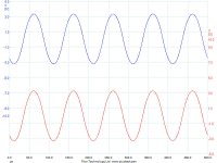
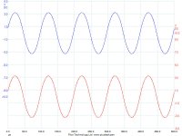
I got these measurements done a little early:
+/- 40VDC on rails of Krill output stage
Output 23 VRMS at into 8 ohm load which is just a few volts below the onset of clipping
In the next 3 posts, the signal at the input to the Krill o/p stage is in the lower trace. The upper trace was measured at (1) base of driver Q13; (2) emitter of driver Q13; and (3) emitter of output Q14. Transistor designations are from the schematic in post 1460.

Ok Phil - Where Ya hiding the switching at???? 😀 I know it's gotta be in there somewhere - 'cause those that know sez so...... 🙄
Nice work!!
I hope that this can inspire others to construct and post also. I got some more parts in today - my boards are finished (except for mounting to the OP's 'n heat sink. Should be firing up by this weekend!
Nice work!!
I hope that this can inspire others to construct and post also. I got some more parts in today - my boards are finished (except for mounting to the OP's 'n heat sink. Should be firing up by this weekend!
Hi Scott,
We were posting at the same time so please don't take my remarks in my earlier post as a personal thing.
We were posting at the same time so please don't take my remarks in my earlier post as a personal thing.
scott wurcer said:The currents in the output transistors would suffice. Please adjust the bias to 25mA first.
These voltage waveforms will not show switching of the output devices anyway. What you need is a differential CRO probe and a small value resistor in the collector lead of one of the output devices to view its actual current.
Cheers,
Glen
If by non switching someone mean a few mA (1..3) current passing through an output BJT when the other is in full conduction, then this output stage is indeed a non switching OPS 🙂
This may be a result of cross conduction mechanism 😉
This may be a result of cross conduction mechanism 😉
Roender,
Initially, the argument of the naysayers was that "there couldn't be any switching going on & this needed to be exposed as the sham that it is".
I hope I'm wrong but I suspect that the argument will now change to the small amount of current in the non-active device has no sonic consequences or indeed the measurements are inconclusive, as per Glen.
If not, it would be gracious of those who banged on about this for so long now apologise to Steve.
roender said:If by non switching someone mean a few mA (1..3) current passing through an output BJT when the other is in full conduction, then this output stage is indeed a non switching OPS 🙂
This may be a result of cross conduction mechanism 😉
I was hoping someone would do a DC (or near DC) sweep simply measuring the voltage differentially across the .22 Ohm resistors to eliminate the dynamic confusions.
Unfortunately, I have to agree that what you already did is not telling much about the collector current, which ultimately decides if the output stage is switching or not. As you have a two trace scope, I hope it also has ADD and INVERT functions. If so, here's how you can replace a differential probe:
- Connect a small resistor R (1ohm will do) in series with one of the output transistor collector, say between the upper transistor and the positive power supply rail.
- Connect one probe (CH1) at the collector.
- Connect one probe (CH2) at the positive power supply rail.
- Select proper ranges for CH1 and CH2, to allow both traces on the screen.
- Power up the amp.
- Press INVERT on CH2 and watch the trace go down to minus the supply rail.
- Press ADD. The single trace on display shows the collector current and if R is 1ohm, the indication is in amps.
You need to be very careful in calibrating the null points and to compensate for any scope channels offsets and gain mismatches. Use the variable gain controls if in need. It's difficult, but it can be done with very good precision.
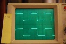
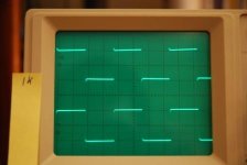
Some osciloscope images.
As you can see my frequency generator is of low quality.
The upper signal is the input. The bottom signal is from output.
Load was a 4,7 ohms resistor.
About 10W power output.
The frequency is the one written on the yellow paper attached to scope.
As you can see my frequency generator is of low quality.
The upper signal is the input. The bottom signal is from output.
Load was a 4,7 ohms resistor.
About 10W power output.
The frequency is the one written on the yellow paper attached to scope.
Attachments
- Status
- Not open for further replies.
- Home
- Amplifiers
- Solid State
- Krill - The little amp that might...