Hi, Bear,
Discussing about graphs, I also found something interesting about "non-turnoff" topology (not restricted to Krill system).
If we look at the page that Ostripper pointed, http://71.203.210.93/upload/
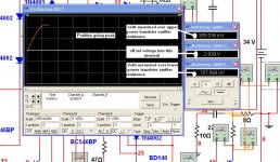
and read paper "Tanaka_AES.pdf", we can see that beside eliminating distortion sharp peak at 20khz (scope shoot), this "non turn-off" is getting better and better at higher frequencies (20khz, 50khz, 100khz)
I found this interesting, because this non-turnoff scheme works better and better in area where negative feedback cannot do much (due to lost of OL in higher frequencies).
Discussing about graphs, I also found something interesting about "non-turnoff" topology (not restricted to Krill system).
If we look at the page that Ostripper pointed, http://71.203.210.93/upload/
and read paper "Tanaka_AES.pdf", we can see that beside eliminating distortion sharp peak at 20khz (scope shoot), this "non turn-off" is getting better and better at higher frequencies (20khz, 50khz, 100khz)
I found this interesting, because this non-turnoff scheme works better and better in area where negative feedback cannot do much (due to lost of OL in higher frequencies).
Attachments
The population is automatically decided by the man intentions
if you want people to build you present things ready to go and offer support Ostry.... mechanicall support Ostry.... boards to offer them to build...tested circuit and avoid to enter theoric discussions not to loose focus, not to go out from the target.
When you want to discuss theories, or want to know if can be done better, if someone has suggestions to improve, or help you to design... then you present circuit open to be modified, evaluated or anything than to build...that gonna be exception.
I am one of the forum guys that had hundreds of circuits i have created/copied/developed/forced to work/designed... well.... make your own choice (up to you).... built!.... i had them built!.... this may give you an idea that at least i know what is good to attract builders.
I had informations from Steve (posted) and from his friend (Jennings) about his intentions..... monthes ago... things happened using direct mail that have not appeared into the forum.... the idea was to be happy cooperating...finding a way to return to electronics even having some health problems, to see people building and using his ideas...to be usefull, helpfull to our communitty.... nice feelings.... different than pride, much better than selfish, not even thinking in money.
So,
Who i am?..... someone that HAD some informations that allowed me to think about and to realise what may be good and what may be bad.... someone that tried to help HIM, not to help me... to help him is to make him happy, watching people building not discussing his ideas or evaluating good or bad his decisions made into the schematic...he would not to be alike into a trial beeing judged.
Evaluate the thread by the results..... how many units built?
That sort of question may be peacefull in your language...in my language it is a hard provocation Ostry..... in this peace of land... this tone and question results in figth with knives... some cultural details only... scratch the face in some way in Japan seems invitation to sex relationship...just culture
Third world .... maybe because of that.... as i love you i understood as non provocative...this time.
Schwatznegger would said... "as i love you, gonna kill you in the last place"
ahahahahahah! (kidding Ostry...do not bother...i have good mood)
Logic also determine things, decides things...because obvious only... we do not sell refrigerators into the North Pole... because obvious.
regards,
Carlos
I am one of the forum guys that had hundreds of circuits i have created/copied/developed/forced to work/designed
You said it.. hundreds.. I can't afford to build hundreds to
"get it right". before I even build 1, I at least will make sure
that it works the best it can and will not end up in the "bin".
As I said before, some of us build to learn, not just to build.
It is cheaper to go on EBAY and buy a used amp than it is to
DIY, so some other purpose is at work here.
Steve has explained the theory of operation in his thread
and had caught the attention of even the "greats" (JC , BC
etc).
As far as thread count , the blowtorch preamp thread
outposts more than all the others (including yours)
, put together.. so , that proves that some discuss , rather than
build. WE who discuss also tend to build less , but we still
build.
Betcha for every DX amp in the world there are a hundred "leaches"...

OS
My English is terrible....hundreds of guys assembled
I have not hundreds of schematics...maybe three or four... and all them almost the same...inspired into an old Aksa model.
Bye Ostry...be happy...i will take care of my health.... argue and discussion ending now...will not talk about that subject anymore.
I love peace, cooperation and harmony.
See you next Christmas.
Carlos
megajocke said:
It wouldn't be exactly the same due to the way the input signal is brought to the output stage - it is applied to the collectors of the biasing circuit. Usually the collector would be a current source so the signal wouldn't be able to get through but in this case the transistors are running almost saturated with about 0.2-0.3Vce. Some nonlinearity will be produced here but I don't know if it cancels some distortion from the output stage or if it increases it.
If output bias is increased, giving these transistors more Vce so they work in the linear (?) region there will be a region of decreased transconductance for the output stage, when saturation moves from the first to the other transistor. This will usually not be at 0A output current because of non-identical current gain of positive and negative half.
(see http://www.diyaudio.com/forums/attachment.php?s=&postid=1686992 for a plot of output impedance vs output current in this case. Middle hump in output is because of an underbiased output stage and the hump at 4A is when saturation moves from one bias transistor to the other)
Steve wrote earlier that there is a distortion null at some output stage bias current. If bias current is increased beyond this, distortion will rise again which can be explained this way (at low bias both transistors will always be saturated).
You understand how this bias circuit works. You are in the minority.
I haven't read this whole thread, but I haven't come across any explanation as to why this scheme ought to be more linear. I'm all ears.

lumanauw, I downloaded the AES article, but did not yet read it. Thanks, OS!!
It seems like the "new bias" circuit has the greatest benefit at the lower power levels, and serves to linearize the "increase" of distortion. The effect at 100kHz. is impressive.
Regarding the bias circuit, and how it works. I am slow to follow along until I spend some time with unfamilliar designs, unlike some others that have instant recognition and understanding. Of them I am envious. But, it seems to work simply by not permitting any output device to be swung "off" due to the driver's signal going in the opposite direction of "on".
No glitchie due to cutoff...
Nelson Pass showed us a link to an early 1970s design of his that used simply a diode in series with the base of an output transistor to accomplish the same idea. The Tanaka article is another approach to the same goal.
Oddly enough I had thought of doing this a long, long time ago, but thought that there must be something wrong with the idea since no one had apparently (Nelson had...) tried to do it before. Silly me. Could have been "famous"!
This all gets me thinking... might the "grain" that I oft notice with some designs of otherwise reasonable power amps be due to this particular source of "distortion"? So, if one made a change to the circuit to avoid the cutoff would the grain go away?
Anyone gonna try it?
Anyone going to build an output stage and show us some real results?
_-_-bear
bear said:No glitchie due to cutoff...
The Tanaka circuit is pretty obvious. The Krill is not the same. It looks to me like the Krill will cut-off the output transistors just like a fixed bias scheme.
bear said:
Anyone going to build an output stage and show us some real results?
_-_-bear
Hi Bear
 I have the parts (including the new ones from when Steve changed some values) for two 50W monoblock amps. Things came to a halt when Steve wanted to change things (for the better) and had to send me the new parts (at no cost to me I might add). Well now I have run into another delay in that my Spousal Unit has decided to help the local economy by repainting all of the rooms in the house - and that starts today. Soooooo maybe by this weekend I can get things back on track and get at least one amp assembled (I still need to do something about a case tho). I have a scope that will do some things - but would need to go over to Steve's and use his distortion meter to get some THD measurements, etc.
 Hi Carlos! Ostripper has asked many questions - BUT he has also made many positive comments and pointed out some ways to make a better amplifier (making a better amp is his quest). I think that this is good. Plus - he is another Tennessee guy and we don't mind telling each other (or anyone else) what we think about things. This sometimes results in some cuss'n (profane language) and bare knuckle contest - but it's mostly well intended. I'm was raised in Texas - and if we don't care for what ya all are saying we would toss your rear-end into the pasture where the stud bull was at. If you came out in one piece then all was forgiven and we would go drink some beer and chase women (in Texas they can be even more dangerous than the bull).

Attachments
don't forget
http://www-f9.ijs.si/~margan/Articles/Class_B_Dist.pdf
Bear
I built these and liked them a lot
regards
Max
http://www-f9.ijs.si/~margan/Articles/Class_B_Dist.pdf
Bear
I built these and liked them a lot
regards
Max
Hi Steve,
first listening impressions? Well i had to move the hole thing in my living room to use better speakers...
The krill mono amp is playing very well! There is a very strong bass. Human voices are reprocuced in a very high resolution. I heard some very dry saxophones ... cool!
Btw: I used a single voltage supply, there is no doubler (yet).
I think i have to do the other channel to compare it with my other amps (DX, DX HR2, EL34 Tube amp)...
R15 is connecting the bases of q9 and q12 in "my" schematic. Its value is 68k. Do you mean this one?
heinz said:Hi Steve,
first listening impressions? Well i had to move the hole thing in my living room to use better speakers...
Try these!

BTW - Congratulations on your construction - hope to get mine done soon! 🙄
Attachments
heinz said:Hi Steve,
first listening impressions? Well i had to move the hole thing in my living room to use better speakers...
The krill mono amp is playing very well! There is a very strong bass. Human voices are reprocuced in a very high resolution. I heard some very dry saxophones ... cool!
Btw: I used a single voltage supply, there is no doubler (yet).
I think i have to do the other channel to compare it with my other amps (DX, DX HR2, EL34 Tube amp)...
R15 is connecting the bases of q9 and q12 in "my" schematic. Its value is 68k. Do you mean this one?
No, I meant R9 as mentioned by Thomas. R15 is correct. If the board you are using has R9 connected from +36V to -36V then the value shown is correct. Anyone using boards they got from me should change the value of R9 to 33K.
I need to update the schematic and post it again with the things Thomas is finding while stuffing his boards. I was trying to wait until he was finished finding things.
Sounds really good... my Dx Amplifier cannot compete...no chance for my toy!
The Krill sounds better... despite my recordings have not shown that (youtube).... into real world you "feel" immediatelly the advantage for Krill.
I was simulating....playing only, as i can do that layed down when i wait the fever temperature to drop (now an infection)... and was not hard to see transistors never switch off...never cut!.... this makes the difference ... one of the best effects (results) you have with class A without all that heat.
Of course people is turning green because of envy..of course!...he did!.... Steve Did it!.... a good moment to eat your pride folks... always appear someone that knows more than we know.
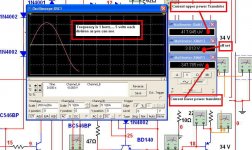
I found something i cannot explain...a subproduct.... an offset result of this trick (clever) swing into the output level potential (consequence is a swing)... i found almost 3 volts.... same i found (2.5) when i assembled the first time.... i am not an engineer..also i do not understand electronics so deep to understand..but at least i understood how the amplifier works...beautifull...just beautifull!
I do not think i have an amplifier, now a days, in my home, that can beat the krill..... but will test once more with more guys evaluating.
This test i have made is simple.... i have adjusted input condensers (when had) and feedback gain condensers to allow amplifiers to operate into 1 cicle each second..... Krill had not the need to adjust that..can operate 1 tenth of second into the simulator..... into low frequency you can measure and have time to simulator to produce readings of current into transistor emitters...so i could see they never switch off...always conducting from colector to emitter...and both conducting...and always.
I do not know if this off set i had (had not so big trying my amplifier this same way) will be canceled....as plus and minus can be zeroed...or not..... well.... i would tolerate that 1 watt there to listen all that sound quality if this remains there into my final construction (a friend will do for me...he is very slow...i have to wait..i am sick now a days.
Be happy.... do not build Dx Amplifier if you want the best possible sound..build Krill!
Dx Amplifier will make you happy..for sure it will...but Krill is better..... CLEARLY BETTER!
regards,
Carlos
The Krill sounds better... despite my recordings have not shown that (youtube).... into real world you "feel" immediatelly the advantage for Krill.
I was simulating....playing only, as i can do that layed down when i wait the fever temperature to drop (now an infection)... and was not hard to see transistors never switch off...never cut!.... this makes the difference ... one of the best effects (results) you have with class A without all that heat.
Of course people is turning green because of envy..of course!...he did!.... Steve Did it!.... a good moment to eat your pride folks... always appear someone that knows more than we know.
I found something i cannot explain...a subproduct.... an offset result of this trick (clever) swing into the output level potential (consequence is a swing)... i found almost 3 volts.... same i found (2.5) when i assembled the first time.... i am not an engineer..also i do not understand electronics so deep to understand..but at least i understood how the amplifier works...beautifull...just beautifull!
I do not think i have an amplifier, now a days, in my home, that can beat the krill..... but will test once more with more guys evaluating.
This test i have made is simple.... i have adjusted input condensers (when had) and feedback gain condensers to allow amplifiers to operate into 1 cicle each second..... Krill had not the need to adjust that..can operate 1 tenth of second into the simulator..... into low frequency you can measure and have time to simulator to produce readings of current into transistor emitters...so i could see they never switch off...always conducting from colector to emitter...and both conducting...and always.
I do not know if this off set i had (had not so big trying my amplifier this same way) will be canceled....as plus and minus can be zeroed...or not..... well.... i would tolerate that 1 watt there to listen all that sound quality if this remains there into my final construction (a friend will do for me...he is very slow...i have to wait..i am sick now a days.
Be happy.... do not build Dx Amplifier if you want the best possible sound..build Krill!
Dx Amplifier will make you happy..for sure it will...but Krill is better..... CLEARLY BETTER!
regards,
Carlos
Attachments
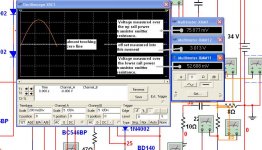
Yes folks..of course the off set was adjusted to less than 1 milivolt without signal
into the input.... this have appeared dinamically.
This hell off set is "the ghost in my life... fantasma"..... always bothering me....but do not disturb sonics.... sound is awsome!
regards,
Carlos
Build Krill!
into the input.... this have appeared dinamically.
This hell off set is "the ghost in my life... fantasma"..... always bothering me....but do not disturb sonics.... sound is awsome!
regards,
Carlos
Build Krill!
Attachments
Re: Yes folks..of course the off set was adjusted to less than 1 milivolt without signal
Hi Carlos,
I am not sure what the offset shown in your simulations is. A real version of the amp will have less than 1/10th that offset before adjustment.
When the offset is adjusted, you should make the adjustment with your regular source (such as your preamp) plugged into the amp input, but with no signal.
destroyer X said:
into the input.... this have appeared dinamically.
This hell off set is "the ghost in my life... fantasma"..... always bothering me....but do not disturb sonics.... sound is awsome!
regards,
Carlos
Build Krill!
Hi Carlos,
I am not sure what the offset shown in your simulations is. A real version of the amp will have less than 1/10th that offset before adjustment.
When the offset is adjusted, you should make the adjustment with your regular source (such as your preamp) plugged into the amp input, but with no signal.
Yes... i really think so Dunlap...must be something from the simulator that has delay
to reduce the offset to zero (reading) when passing into the zero volt reference line.... i think so.... when the "inside calculator" finishes to calculate the zero the wave form is already in another advanced positive or negative point.
Well...it is a simulator..not the real thing...the real amplifier sounds delicious.... i do not trust simulators...they are nice tools only...the judgement is made by human ears.
Thank you very much, once again and again, because you have shared with us.
I am deeply honored with your attention.
Carlos
Hi, Steve,
In earlier page, you mentioned about using Q7,8,10,11 for thermal compensation by attaching those to heatsink.
Is this better/worse than attaching the bias diodes in the heatsink?
In earlier page, you mentioned about using Q7,8,10,11 for thermal compensation by attaching those to heatsink.
Is this better/worse than attaching the bias diodes in the heatsink?
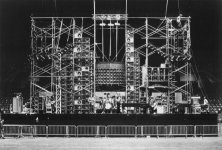
If anyone wondered what the mythical beast I made the outlandish claims about might have looked like (if it were indeed real), try this link.
http://www.diyaudio.com/forums/showthread.php?postid=1685447#post1685447
The amp in the picture is a 200WPC stereo amp. The 400W amp looks the same, but is 20lb heavier. I no longer have any of the 400W amps here. I do have the 200W amp because UPS was nice enough to destroy it for me. I have no idea what they did, but boards were torn loose and the potted toroidal transformers were broken loose from their mountings. It doesn't show in the picture, but they even bent that 1 inch aluminum! Maybe they should land the plane before they off load packages.
lumanauw said:Hi, Steve,
In earlier page, you mentioned about using Q7,8,10,11 for thermal compensation by attaching those to heatsink.
Is this better/worse than attaching the bias diodes in the heatsink?
The tracking is pretty much the same either way. Just slightly faster with the diodes because of their lower thermal mass.
I chose to put the diodes on the heat sink because I didn't want to buy a larger heat sink to accommodate 4 more transistors. The diodes only require one hole for mounting and can be placed very close to the outputs at the center of the heat sink.
I would have also needed to make the board wider to move those transistors to the edge for mounting to the heat sink.
- Status
- Not open for further replies.
- Home
- Amplifiers
- Solid State
- Krill - The little amp that might...