mfc said:Here is a variation of just the output stage alone that does under .005% THD 20v peak into 8ohms at
20Khz.
That's 50W in 8ohm. Have you built and measured it?
I still want to see a shred of proof of this claim:
http://www.diyaudio.com/forums/showthread.php?postid=1752556#post1752556
I've tried to build something similar some time ago, and it's a living hightmare to set up. You'll never get distortion cancellation at all frequencies and loads.
http://pagesperso-orange.fr/francis.audio2/AmpHegglun.doc
Thank you everyone for your support. No matter what what any one says, the amps were built and tested. I have never and will never post anything I have not built and tested without clearly stating that. The only thing I have posted so far that I did not build and test is the servo circuit that I changed as a result of input form AndrewT.
Some have ask me to prove my claims made in the Blowtorch thread. I am not sure want they want that they will accept. If they will kindly tell me just what I need to do, then I will try to oblige them.
Some have ask me to prove my claims made in the Blowtorch thread. I am not sure want they want that they will accept. If they will kindly tell me just what I need to do, then I will try to oblige them.
syn08 said:
That's 50W in 8ohm. Have you built and measured it?
I still want to see a shred of proof of this claim:
http://www.diyaudio.com/forums/showthread.php?postid=1752556#post1752556
I've tried to build something similar some time ago, and it's a living hightmare to set up. You'll never get distortion cancellation at all frequencies and loads.
http://pagesperso-orange.fr/francis.audio2/AmpHegglun.doc
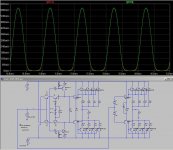
I just downloaded and ran mfc's LTspice sim (see attachment).
It is actually only 20V into 8 ohm (25W) with four pairs of output devices 🙄
I ran two versions in parallel - mfc's Krill OPS and one without the Krill bias generator (with ideal voltage sources for biasing instead).
The bias of this version ( call it a standard double EF) was adjusted so that Iq is exactly the same as in the Krill version.
Note the superimposed green and red current plots. These are the emitter currents for the first NPN transistor of each output stage - they are identical and note that the krill bias generator does absolutely nothing different to the cross over region Iq.
At 1kHz, 2kHz and 5kHz the THD of the double emitter follower version is much better than the krill version (about half).
At 20kHz though there is an interesting harmonic cancellation effect happening (with resistive load) and in this instance the krill version is returning a lower THD than the double EF.
Cheers,
Glen
Attachments
Watch out OS or Cordell will hit you with the "static" crossover distortion that is not eliminated with these non-switching OPS - only eliminated with Class A.
syn08 said:
That's 50W in 8ohm. Have you built and measured it?
I still want to see a shred of proof of this claim:
http://www.diyaudio.com/forums/showthread.php?postid=1752556#post1752556
I've tried to build something similar some time ago, and it's a living hightmare to set up. You'll never get distortion cancellation at all frequencies and loads.
http://pagesperso-orange.fr/francis.audio2/AmpHegglun.doc
That sounds simple enough. You couldn't, so I can't.
G.Kleinschmidt said:
I just downloaded and ran mfc's LTspice sim (see attachment).
It is actually only 20V into 8 ohm (25W) with four pairs of output devices 🙄
I ran two versions in parallel - mfc's Krill OPS and one without the Krill bias generator (with ideal voltage sources for biasing instead).
The bias of this version ( call it a standard double EF) was adjusted so that Iq is exactly the same as in the Krill version.
Note the superimposed green and red current plots. These are the emitter currents for the first NPN transistor of each output stage - they are identical and note that the krill bias generator does absolutely nothing different to the cross over region Iq.
At 1kHz, 2kHz and 5kHz the THD of the double emitter follower version is much better than the krill version (about half).
At 20kHz though there is an interesting harmonic cancellation effect happening (with resistive load) and in this instance the krill version is returning a lower THD than the double EF.
Cheers,
Glen
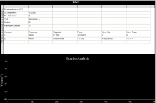
That is interesting Glen. Here is a larger power version with
40v peak into 8ohm (200w) at 20Khz and under .005%. Try it.
Nope, not built - just poking around.
Mike
Attachments
mfc said:
That is interesting Glen. Here is a larger power version with
40v peak into 8ohm (200w) at 20Khz and under .005%. Try it.
Nope, not built - just poking around.
Mike
Running out of time ATM unfortunately, however my main point is that with enough output devices in parallel these low THD figures can be easilly had in simulation just the same with just a bog standard double or triple EF.
None of these simulations prove one way or the other that the krill circuit is doing anything remarkable, IMHO.
Cheers,
Glen
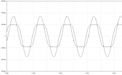
MJL21193 said:I ran it in Multisim.
It has low distortion ( I got .005% but at 1Vpk - .01% at 20Vpk)
That was at 1k. Odd, but like Glen said, it's a lot lower at 20k:
Attachments
jkeny said:Watch out OS or Cordell will hit you with the "static" crossover distortion that is not eliminated with these non-switching OPS - only eliminated with Class A.
Hi Jkeny,
Thanks for reminding me!
Some of the non-switching arrangements have the potential for reducing some contributors to dynamic crossover distortion (an important distortion, make no mistake), but they generally do not help much with static crossover distortion.
Cheers,
Bob
G.Kleinschmidt said:
Running out of time ATM unfortunately, however my main point is that with enough output devices in parallel these low THD figures can be easilly had in simulation just the same with just a bog standard double or triple EF.
None of these simulations prove one way or the other that the krill circuit is doing anything remarkable, IMHO.
Cheers,
Glen
Well stated, Glenn.
Cheers,
Bob
I just ran GK's sim (EF vs. krill ) and found something interesting.
To be fair I used Andy C's signal source , Known good models
(andy's 2sa4793/2sa1837,FJP5200/1943 , Ksa1381/3503).
there is one factor here that "stacks the cards' in favor
of the EF .. the simulated voltage sources.
In the A/B comparison I noticed the EF "acted" much different
then when simulated by a real VAS. I suspect the ideal V
sources , with their infinitely low impedances, "optimized'
the EF giving it a unfair advantage.
would it not be a more objective exercise to compare
the krill current amp to the EF using a known low distortion
input/vas instead of the "ideal sources" ??
OS
ostripper said:I just ran GK's sim (EF vs. krill ) and found something interesting.
To be fair I used Andy C's signal source , Known good models
(andy's 2sa4793/2sa1837,FJP5200/1943 , Ksa1381/3503).
there is one factor here that "stacks the cards' in favor
of the EF .. the simulated voltage sources.
In the A/B comparison I noticed the EF "acted" much different
then when simulated by a real VAS. I suspect the ideal V
sources , with their infinitely low impedances, "optimized'
the EF giving it a unfair advantage.
would it not be a more objective exercise to compare
the krill current amp to the EF using a known low distortion
input/vas instead of the "ideal sources" ??
OS
Hi OS,
This is a good point. I have seen differences in output stage behavior depending on whether they are driven by ideal voltage sources or VAS. These differences do tend to be quite a bit less when a Triple EF is used (as you know, I am a very strong advocate of the Locanthi "T" circuit).
Nevertheless, you are right; comparisons are best done using a real, "known good" VAS in a proper apples-apples comparison.
Cheers,
Bob
Steve Dunlap said:Some have ask me to prove my claims made in the Blowtorch thread. I am not sure want they want that they will accept. If they will kindly tell me just what I need to do, then I will try to oblige them.
Okay, you've made the claim of an amp with no global NFB having THD at 20 kHz, 400W into 8 Ohms of 0.005 percent.
How about starting out by summarizing what you've already provided so far about the topology or any other design details you may have of this amp? That should be very easy to answer and would get everyone on the same page.
Steve Dunlap said:Are you referring to my design? What I am doing is quite different from the schematic in your thread.
Mmmmm... Well yes and no. Both designs exploit nonlinearity
in the signal path. I have high speed diodes that cut off and you have
drivers that saturate.
I have another question, though. You have a 4.7 uF capacitor across
the Bases of drivers Q13 and Q15. and it looks like you can't charge
it with greater than about 10 mA. Doesn't this create a condition with
high frequency transients where the bias voltage across the cap must
remain relatively constant? If the output stage needs an extra 0.5V to
keep both Q14 and Q16 in forward conduction, it's not going to get it
for a couple hundred microseconds.
😎
Bob Cordell said:Nelson has sure learned a lot since then 🙂.
Aren't you happy that I didn't put it into production like Panasonic?
😎
Nelson Pass said:
Mmmmm... Well yes and no. Both designs exploit nonlinearity
in the signal path. I have high speed diodes that cut off and you have
drivers that saturate.
I have another question, though. You have a 4.7 uF capacitor across
the Bases of drivers Q13 and Q15. and it looks like you can't charge
it with greater than about 10 mA. Doesn't this create a condition with
high frequency transients where the bias voltage across the cap must
remain relatively constant? If the output stage needs an extra 0.5V to
keep both Q14 and Q16 in forward conduction, it's not going to get it
for a couple hundred microseconds.
😎
OMG!
Somebody else has an intuitive grasp of what I was trying to explain here:
http://www.diyaudio.com/forums/showthread.php?postid=1753180#post1753180
Cheers,
Glen
Nelson Pass said:
Mmmmm... Well yes and no. Both designs exploit nonlinearity
in the signal path. I have high speed diodes that cut off and you have
drivers that saturate.
I have another question, though. You have a 4.7 uF capacitor across
the Bases of drivers Q13 and Q15. and it looks like you can't charge
it with greater than about 10 mA. Doesn't this create a condition with
high frequency transients where the bias voltage across the cap must
remain relatively constant? If the output stage needs an extra 0.5V to
keep both Q14 and Q16 in forward conduction, it's not going to get it
for a couple hundred microseconds.
😎
I'm not sure which schematic your are looking at. I show a 1uF cap. What frequency would that correspond to with 1uF?
ostripper said:I just ran GK's sim (EF vs. krill ) and found something interesting.
To be fair I used Andy C's signal source , Known good models
(andy's 2sa4793/2sa1837,FJP5200/1943 , Ksa1381/3503).
there is one factor here that "stacks the cards' in favor
of the EF .. the simulated voltage sources.
In the A/B comparison I noticed the EF "acted" much different
then when simulated by a real VAS. I suspect the ideal V
sources , with their infinitely low impedances, "optimized'
the EF giving it a unfair advantage.
would it not be a more objective exercise to compare
the krill current amp to the EF using a known low distortion
input/vas instead of the "ideal sources" ??
OS
I wasn't really trying to draw a comparison against the krill OPS and a double EF, just showing that there is nothing remarkable about getting <0.005% THD in the simulator. I deliberately ran a sim with and without the krill bias generator simply to see what effect the krill bias generator has on the circuit.
Cheers,
Glen
Nelson Pass said:
Aren't you happy that I didn't put it into production like Panasonic?
😎
It wouldn't have mattered. Mine is not the same as yours. Anyway, even greater powers than yours intervened.
- Status
- Not open for further replies.
- Home
- Amplifiers
- Solid State
- Krill - The little amp that might...