c2cthomas --
Sweat heart?!?!?!?!? jeez...............
I hope you meant sweet heart!
or maybe I should say sweet heat
Sweat heart?!?!?!?!? jeez...............
I hope you meant sweet heart!
or maybe I should say sweet heat
PH104 said:c2cthomas --
Sweat heart?!?!?!?!? jeez...............
I hope you meant sweet heart!
or maybe I should say sweet heat
OMG!
 My mistake - apologies to all!

To many solder fumes!!

PH104.... can you please post some evaluation about sonics
Your subjective opinion matters, of course, and related to my person is much more important than numbers you can post.
How it is sounding into your speakers?
What is the other amplifier you use to play together those speakers you may use for testing purposes?
How you compare your standard amplifier with the Krill?.... or... what you perceived as different?
Also inform, please, your other amplifier topologie..if simetrical, bootstrapped, mirrored, using CCS and where or post schematic or link to it...this will be very helpfull to me as i have some idea about how things sounds watching the schematic (more than 4 thousand amplifier built and listened made me "have an idea just watching")
Thanks in advance by your kindness to inform ME something... as numbers to me means half of anything.
ME is because subjectivity is important to my person, much more than nice numbers...what people feel listening, and what is the comparison with their prefered/standard home audio equipment...those are results from your subjectivity and gives me a lot of ideas about.
Also if you have made your home audio...if it is your design or not...this gives me an idea if you can be biased or not.
regards,
Carlos
.............................................................
I just cannot wait to see you building dear Thomas... i hope painting is finishing and wife is giving you a break.
regards,
Carlos
Attachments

Hi
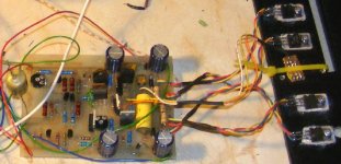
I built one of the boards allready and the other is almost done.
I used small home made heatsinks (about 1,5 X 0,3 inch) in all TO220 Transistors. They still run hot but i can put my finger on them.
I would like to avoid using R32 and R33. I measured the offset and i read +220 mV when the base of Q7 Q10 is set to 0V. Of course I can have 0V offset if i adjust R26. the VAS has +56 – 54V. What do you think about that? Should I use R32 to correct the offset or is it enought adjusting R26? Will i get much more distortion?
I allready heard this half amp, but i will only post my opinion when both are working
Carlos I hope you get better.
Thanks
I now have my build up as a mono amp, (not using SD boards or components) I do have an offset (@-3v) and will look into that shortly. probably due to the components used as this was built from the parts bin to see what the Krill was like. (outputs are TIP41C and TIP42C for example as I have some)
It sounds good 🙂 (Via a cap to kill the offset) This has encouraged me to look to cure the offset and build a stereo pair.
Thanks Steve for posting the design of an interesting amp which works!
alan
It sounds good 🙂 (Via a cap to kill the offset) This has encouraged me to look to cure the offset and build a stereo pair.
Thanks Steve for posting the design of an interesting amp which works!
alan
Thanks martins,
It's often easier to tell the essential sound of an amplifier using one channel only as the ear isn't listening to stereo soundstage, etc
It's often easier to tell the essential sound of an amplifier using one channel only as the ear isn't listening to stereo soundstage, etc
We are getting some good news here!
jmmartins -- Steve is the expert and hopefully he will be available next week. But it is my opinion that it is better to keep the offset and bias adjustments independent so that you can adjust bias to its optimum and adjust offset with R32 and R33. BTW, We are using about the same size heatsinks for the TO-220 transistors. I took my board apart last Friday to match the transistors in the output stage but I can make some voltage measurements when I get it put back together.
Alan -- Are you using the offset trimpots R32 and R33? You and jmmartins have made me anxious to get to the listening tests!
Carlos -- I will work on the answer to your assignment 🙂
I should have the one board re-assembled tomorrow and hopefully will have some results next week.
Phil
I have the trimpots, R32 gives -6 to -2v offset 🙁 However this is not unexpected. This is the 50watt circuit with a homebrew board and a ragbag of transistors (mpsa06, mpsa56, TIP48,41,42) Some investigation is in order, matching Q8 and Q11 would help I guess.PH104 said:We are getting some good news here!
Alan -- Are you using the offset trimpots R32 and R33? You and jmmartins have made me anxious to get to the listening tests!
Phil
Whats amazing is the results from this mess....
Attachments
Hi,
I have similar experience with the offset voltage at the junction of base of Q7and Q10.
SD told me adjust R6 emitter resistor of Q1 from 1K to 1K2 but I ended up using 2K where I manage to set the offset from -1.52 down to 0. and from this all I have to adjust was R31 for the output offset and finally the bias to 30mV accross the two emitter resistor on the output. This is for the 50W.
I'm no expert on this, I just follow what SD told me to check with my build.
I hope with my experience on my build may shed some answer to some of the Krill builders having similar problems.
Regards
Rom
oops
that should be R6 Collector resistor and NOT emitter resistor.
I think I need some coffee too early in the morning
ciao
Rom
that should be R6 Collector resistor and NOT emitter resistor.
I think I need some coffee too early in the morning
ciao
Rom
It's often easier to tell the essential sound of an amplifier using one channel only as the ear isn't listening to stereo soundstage, etc
If you’re right then i must say it is amazing! I can’t tell you if the bass is good or the highs are good or the midrange, but, I like the sound. It is good! It is very good. I can tell the bass lines from a mess of sounds, the heights are soft but clear. I will not tell anything else until I have both working because my perception can be polluted by the fact that I usually hear my music in stereo mode and my words would not be reliable.
I listened with the offset adjusted to 0V by R26 and bias was about 60mA each output transistor (14 mV across R18).
Martins
Hi Phil
I adjust offset with R26 and bias with R27 in the bias diode string. Problem is, i was trying to avoid using R32 and 33 because the chassis i am building is very dificult to install those multiturn resistors. and if i adjust the base of Q7 Q10 to 0V i only get 220mV offset. Let´s wait, maybe Steve can say something about this.
I adjust offset with R26 and bias with R27 in the bias diode string. Problem is, i was trying to avoid using R32 and 33 because the chassis i am building is very dificult to install those multiturn resistors. and if i adjust the base of Q7 Q10 to 0V i only get 220mV offset. Let´s wait, maybe Steve can say something about this.
Very good Martins,
It seems that you like the sound in mono which is a great indicator of sonics to come. Looking forward to your full stereo report.
It seems that you like the sound in mono which is a great indicator of sonics to come. Looking forward to your full stereo report.
Hi Martins --
I was confused about how you were adjusting offset and and now see how you are doing it. I'm curious -- have you measured the offset of the output stage with the bases of Q7 and Q10 grounded? And thank you for your preliminary listening report. It seems like I will like these amplifiers. Now I really can't wait to listen.
My soldering iron is calling me and I have leave. 🙂
Phil
unmibh said:Hi,
SD told me adjust R6 emitter resistor of Q1 from 1K to 1K2 but I ended up using 2K where I manage to set the offset from -1.52 down to 0. and from this all I have to adjust was R31 for the output offset and finally the bias to 30mV accross the two emitter resistor on the output. This is for the 50W.
Regards
Rom
Thanks for the info, 2.2K gave just enough adjustment to 0 the offset . Now time to change the outputs (this will blow a tip41/42 in short order if I test properly
 ) time to look in the junk box fo some output transistors 🙂
To follow up, replaced the outputs Q13,Q14,Q15 and Q16 with a pair of power darlingtons (MJ11015 and MJ11016) Still sounds good and now can run some power without letting the magic smoke out.
Steve if you read this, whats your take on using power darlingtons instead of the output pair? I build rather than run simulations and it still seems to work very well. 😎
Steve if you read this, whats your take on using power darlingtons instead of the output pair? I build rather than run simulations and it still seems to work very well. 😎
Spiny said:
Thanks for the info, 2.2K gave just enough adjustment to 0 the offset . Now time to change the outputs (this will blow a tip41/42 in short order if I test properly
No Problem I'm happy that the same resistor change work out with you.
Interesting to know that it also work with darlington pairs.
I may try that too.
Rom
have you measured the offset of the output stage with the bases of Q7 and Q10 grounded?
Hi Phil
With R26 I adjusted the bases of Q7,Q10 to 0V (not grounded) and that way i get an offset of about +220mV (in the output).
If I want 0V, output offset, I can achieve that adjusting R26, but that way I get about -220mV in the base of Q7 andQ10
There are 2 offset’s to adjust. The first one (VAS offset) is the collector of Q4 Q6 (base of Q7 and Q10) that should be set to 0V and the second one is the output offset that should be set to 0V with R32 or R33. Now, as I am trying to avoid using R32, I have only one resistor to adjust both - (R26). When I increase the Volts in the bases of Q7 Q10 I increase also the Volts in the output, so I will always get an offset; in the base of Q7 or in the output.
My doubt is: this small VAS offset has a big negative impact in the input transistor pair (Q1 Q2) or not?
Thanks
Andypairo said:
Hi Steve,
may I ask why is better to connect R9 to the negative supply?
Ciao
Andrea
It keeps the draw on the power supply balanced and keeps that current out of the ground return.
- Home
- Amplifiers
- Solid State
- Krill construction thread - 100W version