Aaron,
Would you please explain your square response in more detail, loaded and unloaded? Also, what was your input voltage? The ringing and overall response would be affected by all of them. Unless your 4ohm dummy load was at least 20W, I suspect your input voltage was very low. I only loaded mine with the 8R2 12W cemented resistor while saving the waveforms (about 5seconds), and that period was enough to leave a burn mark on my workbench on one of the measurements.
Lastly, which value did you use for C105/106, and C101? The slope of the square would be affected by both values. The slope isn't a critical aspect, as long as it is within bounds - the P3A's slope is much worse, not even to mention those of the earlier versions when people used 330pF - there the slope was almost 45degrees even at 10kHz, and apparently the sound was still excellent and "Krell-like". IMO ringing problems are far more severe than the slope, which is why I think my 22pF for C105/106 is too small. If only it wasn't almost so difficult to get to them I would have repeated the measurements with 47pF or so.
I guess the best way would be to measure the original Krell and derive the optimal value for C105/106 from its square wave response; I'll try to fit that in that sometime next week.
I still have to lay my hands on a proper thermometer for solid materials. I use as reference the assumption that 60degrees celcius is the pain threshold for a finger directly on the top of the metal can. At 440mA bias per transistor, 7 of the 8 is cool enough for me to hold my finger on (just), and the other one is much warmer. The cubes themselves are pretty cool, I guess below 40degrees. That is probably because I have a much higher fan speed, open enclosure and around 15degrees ambient winter temperature. I guess if it wasn't for the problematic transistor it would have been possible to push them to about 600mA (remember its not linear)for 90W class-A in 8ohms to get all 8 devices to run as hot as on the KSA100. I recently reduced my friend's KSA100's bias from 100W to 70W to make it run cooler and the sound didn't change at all, a sign that at a certain point it just doesn't make a difference anymore. I think 60W or so into class-A is more than enough, unless you're running absurdly low-impedance speakers. For standard 4ohm or so there's no need to go beyond that.
Why not measure it with 33, 47, or 68pF in polystyrene?
Assuming they can be had easier than silver-mica in SA, of course.
(sidenote: 😛olystyrene's have better accuracy than silver-mica, 1% instead of 2)
Are you planning to measure overshoot as well, with/without cap on the output?
imo, thermal stability has a lot to do with sound quality.
Assuming they can be had easier than silver-mica in SA, of course.
(sidenote: 😛olystyrene's have better accuracy than silver-mica, 1% instead of 2)
Are you planning to measure overshoot as well, with/without cap on the output?
imo, thermal stability has a lot to do with sound quality.
Hi PWatts,
your slope on the 20Hz square wave is indeed slight.
The ringing into the zobel is I believe of no consequence since it is the natural frequency of your 100nF, about 200kHz.
But look at your 20kHz squarewaves. You have an oscillation at about 2MHz (at the top corner after the leading edge). You must stop this.
Can you experiment with some alternative Zobel values(150nF and/or6r8) and maybe even add the full Thiel network onto the output.
PWatts,
Regarding HF osc, What does the signal from the generator look like? Do you have the Same kind of ringing at 2Mhz??
Can you post both generator signal and output in the same pic?
\Jens
Regarding HF osc, What does the signal from the generator look like? Do you have the Same kind of ringing at 2Mhz??
Can you post both generator signal and output in the same pic?
\Jens
PWatts said:Aaron,
Would you please explain your square response in more detail, loaded and unloaded? Also, what was your input voltage? The ringing and overall response would be affected by all of them. Unless your 4ohm dummy load was at least 20W, I suspect your input voltage was very low. I only loaded mine with the 8R2 12W cemented resistor while saving the waveforms (about 5seconds), and that period was enough to leave a burn mark on my workbench on one of the measurements.
I ran a 5kw dummy load (!!!) @ 4 ohm running at about 50w output, loaded @ 4 ohm... That's all i used and ran a few square waves through, TBH i never tested very hard i was happy as there was no peaking in wierd ways or odd drop off's.
Lastly, which value did you use for C105/106, and C101? The slope of the square would be affected by both values. The slope isn't a critical aspect, as long as it is within bounds - the P3A's slope is much worse, not even to mention those of the earlier versions when people used 330pF - there the slope was almost 45degrees even at 10kHz, and apparently the sound was still excellent and "Krell-like". IMO ringing problems are far more severe than the slope, which is why I think my 22pF for C105/106 is too small. If only it wasn't almost so difficult to get to them I would have repeated the measurements with 47pF or so.
I used 39pf - they were polystyrene - I THINK - they are small and blue - definately aren't silver mica! They seemed to do the job though
I guess the best way would be to measure the original Krell and derive the optimal value for C105/106 from its square wave response; I'll try to fit that in that sometime next week.
Excellent, i can't wait to see the results from the actual krell!! Would be an excellent benchmark...
I'm running approx 130w class A into 4 ohm... That means i get full class A into 8 ohm all the way into clipping...
I run 5 ohm speakers (average ohmage) - so i get about ~140w full class A!
It sounds excellent, i doubt i'd notice a small drop in bias... thats why i've decided to leave it as it is!
Aaron
[edit - the dummy load was from a guy who custom makes resistance banks for power stations!!! I ran it at 2kw for about 2 minutes off another amp and i had to use a fan as the metal was burning hot!!!]
Terry, I'm glad you're sorted, as I haven't had chance to do any measuring for you.
Interesting measurements guys, my experience was that the amp was not so prone to ringing as others seem to have found. I wonder how much PCB layout has to do with stability?
Interesting measurements guys, my experience was that the amp was not so prone to ringing as others seem to have found. I wonder how much PCB layout has to do with stability?
pinkmouse said:I wonder how much PCB layout has to do with stability?
Quite a lot.
And with sound quality in general, all the audio cardinals on this gathering, including Nelson Pope himself, agree on that one.
Read the posts of Mr Greg Ball on the subject.
jacco vermeulen said:Quite a lot.
Yeah, I was always aware of it mentally whilst I was doing the design, but when it actually comes down to real results in the real world I'm always staggered... 🙂
To address everyone's questions first:
jacco: you overestimate parts availability in Africa. Every single component I use, resistors capacitors, transformers, even wiring was imported from overseas. Merely buying a lot of expensive components with our weak exchange rate, freight and import duties just isn't always worth it. Makes you wonder how people here even bother going diy 🙂 I'll try with different values, but it will be cheap ceramic. Otherwise I can try 100pF for the other end of the spectrum, I have some in MKP and silver mica. I seriously doubt if anyone would be able to measure or hear the difference between mica and polystyrene so it's not an issue. Polystyrene is a b*tch to work with though with its thin leads.
AndrewT: see my additional comments and graphs. I did experiment with different zobel values, as well as the Thiel network - no significant change, except in the "character" of the background noise. I'll try investigate the 2MHz oscillation though.
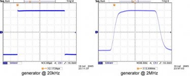
JensRasmussen: I'll add the 20kHz and 2MHz generator response (i.e. directly from generator to scope). 20kHz is almost perfect but with a slight overshoot but no ringing. 2MHz isn't square anymore, but it's still stable. I'll try to get a better generator at the lab sometime, though I doubt it's part of the problem.
NUTTTR: if your 47pF caps are not in a glass-like package they're quite likely not polystyrene, although it is possible. My guess would be polypropylene or perhaps polycarbonate. Not that it really matters, as long as its fairly linear its OK.
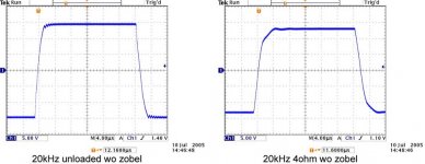
It appears that the amp is a little fussy concerning wiring, perhaps just because of my low 22pF C105/106. The background noise sporadically changed from almost none to audible hum&grain for no reason. It wasn't fan noise, briefly switching them off makes no difference. Reducing the ground wire length from the PCB to the star earth helped, as well as adding a 10ohm resistor in series. The noise is better behaved now, and the ringing also looks much better - even though it is now into 4ohms instead of 8! I didn't repeat all the tests out of laziness, but here is the most severe case: 20kHz square wave unloaded and into 4ohms. The zobel still added a little more overshoot, but much less than with the previous tests so I left it out.
With all my findings I'd seriously recommend not to let C105/106 drop below 33pF - the difference will definitely not be audible, and the stability margin increased. Compare especially the loaded response with my earlier graphs to see what I mean how a small wiring change can make a big difference.
Can anyone else perhaps post their square wave measurements here? I know not everyone has access to a scope capable of saving waveforms, but even some crude manual drawings in MS Paint can be helpful for comparison.
jacco: you overestimate parts availability in Africa. Every single component I use, resistors capacitors, transformers, even wiring was imported from overseas. Merely buying a lot of expensive components with our weak exchange rate, freight and import duties just isn't always worth it. Makes you wonder how people here even bother going diy 🙂 I'll try with different values, but it will be cheap ceramic. Otherwise I can try 100pF for the other end of the spectrum, I have some in MKP and silver mica. I seriously doubt if anyone would be able to measure or hear the difference between mica and polystyrene so it's not an issue. Polystyrene is a b*tch to work with though with its thin leads.
AndrewT: see my additional comments and graphs. I did experiment with different zobel values, as well as the Thiel network - no significant change, except in the "character" of the background noise. I'll try investigate the 2MHz oscillation though.
JensRasmussen: I'll add the 20kHz and 2MHz generator response (i.e. directly from generator to scope). 20kHz is almost perfect but with a slight overshoot but no ringing. 2MHz isn't square anymore, but it's still stable. I'll try to get a better generator at the lab sometime, though I doubt it's part of the problem.
NUTTTR: if your 47pF caps are not in a glass-like package they're quite likely not polystyrene, although it is possible. My guess would be polypropylene or perhaps polycarbonate. Not that it really matters, as long as its fairly linear its OK.
It appears that the amp is a little fussy concerning wiring, perhaps just because of my low 22pF C105/106. The background noise sporadically changed from almost none to audible hum&grain for no reason. It wasn't fan noise, briefly switching them off makes no difference. Reducing the ground wire length from the PCB to the star earth helped, as well as adding a 10ohm resistor in series. The noise is better behaved now, and the ringing also looks much better - even though it is now into 4ohms instead of 8! I didn't repeat all the tests out of laziness, but here is the most severe case: 20kHz square wave unloaded and into 4ohms. The zobel still added a little more overshoot, but much less than with the previous tests so I left it out.
With all my findings I'd seriously recommend not to let C105/106 drop below 33pF - the difference will definitely not be audible, and the stability margin increased. Compare especially the loaded response with my earlier graphs to see what I mean how a small wiring change can make a big difference.
Can anyone else perhaps post their square wave measurements here? I know not everyone has access to a scope capable of saving waveforms, but even some crude manual drawings in MS Paint can be helpful for comparison.
Attachments
Generator signal
Hi,
Did you measure the signal at the insetion point or on the non loaded generator?
I have see ringing on one end of a small signal cable but not on the other end.... just an idea.
\Jens
Hi,
Did you measure the signal at the insetion point or on the non loaded generator?
I have see ringing on one end of a small signal cable but not on the other end.... just an idea.
\Jens
So far I have only heard back from about 1/3 of the people that signed up for the board wiki. If you did sign up and still want boards please e-mail me at the address below. So far there won't be any group buy at a reasonable price unless I hear back from alot more people. I am on the road on a service trip but am able to check in from time to time.
Al, I still have not gotten a good set of board files from you, the last set was corrupted. If you sent them too Advanced thats fine but please let me know.........
Power supply boards will be priced at 14.00 each U.S. currency if we can do a 100 quantity group buy.
Mark
Live from Livingston, Montana......
Mark, if it helps, i can track the profiles from the ones who did not respond yet and send them the word that they should email you.
I can imagine only a portion follows the thread closely.
$14 for the PS boards is very nice.
I can imagine only a portion follows the thread closely.
$14 for the PS boards is very nice.
Al, Mark or someone else, can you please add the link to the Pinkmouse board wiki to your handle?

Not really 😉
This is what I was looking for (but you helped):
http://www.diyaudio.com/wiki/index....rder+Main+Boards,PSU+Boards+and+Output+Boards
This is what I was looking for (but you helped):
http://www.diyaudio.com/wiki/index....rder+Main+Boards,PSU+Boards+and+Output+Boards

jacco vermeulen said:Mark, if it helps, i can track the profiles from the ones who did not respond yet and send them the word that they should email you.
I can imagine only a portion follows the thread closely.
$14 for the PS boards is very nice.
If anyone drops out I'll take a pair or two...
I asked for 4 PSU boards and am dropping from PSU boards , you can have 2 of them. I am still in for the main amp boards.
K-
K-

- Home
- Amplifiers
- Solid State
- Krell KSA 50 PCB