depends...
on the power being pounded through the transistor, and the thermal resistance of the junction to case interface...you'll need to check the datasheets for your devices.
IIRC the die to case thermal resistance for mj21193 is 0.7c/watt, so if you have 30w being dissipated, you will get 21c hotter on the die than the case immediately next to it.
According to Self the top of the to3 case is one of the hottest places on the package and presumably has some sort of thermal material inside, I haven't attempted to verify this...but it sort of makes sense, since it is only minimally air cooled, while the bottom of the package is typically bolted to a big heatsink...
HTH
Stuart
So I have set the Bias pot (normal) so that I read Zero ohms between R125 and Q108 this should be the very lowest Bias point if I understand the relationship correctly. I can adjust the Pot to read up to 4.75K between these two points.
Regards
Anthony
Regards
Anthony
Re: depends...
Thanks stuart....
I think it's a good idea for me to leave the bias as it is

Thanks
Aaron
Stuart Easson said:on the power being pounded through the transistor, and the thermal resistance of the junction to case interface...you'll need to check the datasheets for your devices.
IIRC the die to case thermal resistance for mj21193 is 0.7c/watt, so if you have 30w being dissipated, you will get 21c hotter on the die than the case immediately next to it.
According to Self the top of the to3 case is one of the hottest places on the package and presumably has some sort of thermal material inside, I haven't attempted to verify this...but it sort of makes sense, since it is only minimally air cooled, while the bottom of the package is typically bolted to a big heatsink...
HTH
Stuart
Thanks stuart....
I think it's a good idea for me to leave the bias as it is
Thanks
Aaron
Hi Still4given,
I am getting exasperated.
I told you way back to use the bulb to get you started and to short it out after you proved everything was OK. I also said you could use the bulb as a slow start.
To answer your q. Yes the bulb will glow brighter as you increase the load on the transformer. Yes the Vrail will drop as you load up the bulb.
Check all your voltages and temps are correct without an output stage. Disconnect the power.
Connect the output stage and set bias to minimum, Switch on via the bulb and check your voltages and temps again.
Short out the bulb and start increasing your bias in small steps, I suggested 10W classA on low bias pot and then 20W on the high bias pot.
lgreen said:I hate to ask this-- but why would a driver resistor go? Should I replace my 2 watters with a 5 watters to be safe before I button this thing up?
The driver resistor will go when there is more than 7 volts across it, Mr Green.
Terry switched his output rails, and blew one of the sides.
His front end had the correct voltage on its rails.
The moment one half of the output stage went there will have been a large voltage rise of the other rails on the output.
The feedback works as it should do, it senses the voltage and feeds it back to the input differential stage.
Because of the difference of input versus output voltage, as a result one of the drivers will open up further, voltage on its emitter will increase, current through the 25 ohm resistor will go up, and the resistor will blow.
Under normal circumstances the output voltage will rise with the voltage of the corresponding driver emitter, both having the same sign.
Voltage difference over the 25 ohm Re will remain below 7 volts up till ridiculous output currents.
With your 0.5 ohm Re's voltage across them would be 7 volts minus the voltagedrop from base to emitter of the TO3,around 6.4 volts.
That is ~13 amps per device, over 52 amps output current, constantly.
As your drivers do the job together and the output is not DC, the max output current is sqrt2 higher: some 75 amps.
Is is very common with blown output sections of amplifiers that drivers and emitter resistors are damaged, often these are replaced even if they are still working.
Thanks Jacco. You guys are really teaching us a lot about this stuff, appreciate it.
If yours works like mine, my guess is that even if you have it completely wrong (maxed out rather than minimized) you will still be safe for about 10 seconds to turn it down should you see a large Vre upon a room temp start. I don't get the ability to hit a dangerous Vre until the things start warming up.
Coulomb said:So I have set the Bias pot (normal) so that I read Zero ohms between R125 and Q108 this should be the very lowest Bias point if I understand the relationship correctly. I can adjust the Pot to read up to 4.75K between these two points.
Regards
Anthony
If yours works like mine, my guess is that even if you have it completely wrong (maxed out rather than minimized) you will still be safe for about 10 seconds to turn it down should you see a large Vre upon a room temp start. I don't get the ability to hit a dangerous Vre until the things start warming up.
IT'S ALIVE!
Well, I finally got it working. Whew.
I couldn't wait to get an answer so it took a chance with 24R for the drivers. They seem to work fine. I pulled all of outputs and checked them for shorts, cleaned everything really well, greased them up again carefully mounted them. Then I powered up the boards rechecked all of my measurements. Everything looked good so I hooked them back up to the outputs and brought things up slowly on the variac through the light bulb. I checked voltages everywhere I could think of at each step and all seemed well. I started bringing up the bias and watched the light bulb. When I got to about .128v across RE the bulb started getting brighter so I stopped right there and measured the DC offset. After adjusting it to 0.00v I hooked up some speakers and heard music. So, I took the bulb out of the circuit and gradually increased the bias. At about .300V the amp really started to kick in. I was testing through some book shelf speakers so I couldn't tell just how much kick it has but it sounds very clear.
My studio monitors are packed away right now so will have to get them out this weekend and crank it up a bit. Thanks so much to everyone for all of the help and for not giving up on me. Now to build a case for it. 😀
I would suggest disconnecting the P & N outputs on the boards and power it up. If you are reading more than 1.2v on those output it is set too high. Turn the bias pot until you get the lowest reading there. Reconnect the outputs and start bringing it up while reading the drop across the RE resistors. That worked for anyway.
Blessings, Terry
Well, I finally got it working. Whew.
I couldn't wait to get an answer so it took a chance with 24R for the drivers. They seem to work fine. I pulled all of outputs and checked them for shorts, cleaned everything really well, greased them up again carefully mounted them. Then I powered up the boards rechecked all of my measurements. Everything looked good so I hooked them back up to the outputs and brought things up slowly on the variac through the light bulb. I checked voltages everywhere I could think of at each step and all seemed well. I started bringing up the bias and watched the light bulb. When I got to about .128v across RE the bulb started getting brighter so I stopped right there and measured the DC offset. After adjusting it to 0.00v I hooked up some speakers and heard music. So, I took the bulb out of the circuit and gradually increased the bias. At about .300V the amp really started to kick in. I was testing through some book shelf speakers so I couldn't tell just how much kick it has but it sounds very clear.
My studio monitors are packed away right now so will have to get them out this weekend and crank it up a bit. Thanks so much to everyone for all of the help and for not giving up on me. Now to build a case for it. 😀
So I have set the Bias pot (normal) so that I read Zero ohms between R125 and Q108 this should be the very lowest Bias point if I understand the relationship correctly. I can adjust the Pot to read up to 4.75K between these two points.
Regards
Anthony
I would suggest disconnecting the P & N outputs on the boards and power it up. If you are reading more than 1.2v on those output it is set too high. Turn the bias pot until you get the lowest reading there. Reconnect the outputs and start bringing it up while reading the drop across the RE resistors. That worked for anyway.
Blessings, Terry
still4given said:IT'S ALIVE!
Congratulations, Terry.
Great to read that you got it going, now you in for life, matey !
Looking forward to hearing how much you like your Krell baby.
still4given said:IT'S ALIVE!
Well, I finally got it working. Whew.
Blessings, Terry
Congrats! Hey, how hot does it get?
I can just barely keep my fingers on the heatsink, but not the output transistors, they are too hot to touch. I may have to run it a little lower. I will try to get a temperature gauge of some type to measure. Sure sounds good though. I am anxious to test along side of my P101 and see which sounds better.
Blessings, Terry
Blessings, Terry
My KSA measurements
Hi guys,
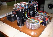
I just finished some measurements on one channel of my test-rig KSA50. I'm building it for a friend who already owns an original KSA100 and KSA200. The entire layout has been copied from the KSA100, including the dimensions, wiring and heatsink & fan assembly. If the result sounds at least as good as the KSA100, it will be rebuilt in a professional copy of the KSA100 chassis.
Specs (per channel) are:
500VA per channel
+-30VDC PSU rails (transformers were already at hand otherwise I would have increased this)
55000uF per rail
4pairs of MJ21194/3 output devices
50W class-A bias
Although I wanted to keep the design as close as possible to the original, some modifications were made.
- twice the number of output devices and heatsink area
- increased PSU capacitance
- MJ21193/4 output transistors rather than MJ15003/4
- DC fuses placed on the busbar for reduced wire length from the PSU
- DC, rather than AC fans with a separate transformer for less injected motor noise
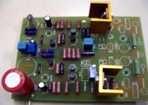
- Top quality components:
- critical resistors are Riken, less critical Holco and the rest Dale
- R127/R128 are 2W 24R Kiwame
- Emitter resistors are 0.5R 5W Mills
- C101 is polystyrene
- C105/106 are 22pF silver mica
- C104/109 are Evox-Rifa 100nF MKP
- C110/C111 are Black Gate Std
- C102/C103 is a single Black Gate 1000uF NX
- All hookup wire is silver coated teflon
- input cable is vD Hul
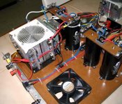
The 22pF value for C105/106 was chosen fairly arbitrarily. I had some trouble with stabilty though, and the measurements suggest that it is perhaps a little too small. 33pF will probably be a better bet, or even as high as 68pF shouldn't be too bad. The bipolar feedback electrolytic was chosen as 1000uF instead of 470uF simply because I got it on sale, and not any other purpose. I chose to hardwire the emitter resistors directly to the output transistors, and regret it now as it means I cannot measure the bias current on each transistor individually. I used an ammeter in place of the DC fuses to measure the total current (1.8A per rail), as the current consumed by the PCB is only about 5% of the total current. To avoid making a mess I used silicone washers instead of mica & thermal compound. This was a mistake as one transistor is running at least 20degrees hotter than the rest, despite all my best efforts to tighten the screws. Even that one is still less than the KSA100 I examined, but if it wasn't for that I could have easily increased the bias with as much as 50%. On all the rest I can place a finger without burning (just), but the problematic one burns to pain in less than a second - it runs at least 80degrees celsius. Besides the obvious problem of reduced lifespan (I'm not too concerned, the KSA100's MJ15003/4's are running that hot for over 20years without trouble), is there any reason why I should go through all the trouble to desolder & replace the transistor?
The predrivers probably didn't need their small heatsinks, and the driver heatsink was sourced from an old PC PSU. It runs a little hot, but still cooler than the KSA100's - I suspect around 50 degrees.
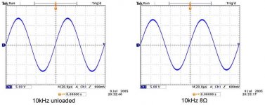
See the pics and measurements I made. The input signals from the generator were checked, they are all perfect. All deviation is therefore done by the amp and not passed from the input. All measurements were with a 1V amplitude (2V p-p) input signal.
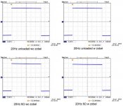
I took a sinewave measurement at 10kHz, unloaded and loaded with an 8ohm load. It looks pretty good on both, no objections there. On the square wave one can learn quite a bit more, comments are welcome. I measured at 20Hz, 1kHz, 10kHz and 20kHz, all loaded and unloaded, with and without a zobel at the output terminals (10ohm & 100nF). It should be noted that squarewave measurements place great demands on a loaded amplifier, much less than sinewaves. I used a 12W 8R2 load resistor and it became scorching hot in less than 5 seconds. I grouped the frequency measurements together in single JPG's (had to compress them a bit) of four measurements each for easy comparison.
20Hz: at that frequency the zobel obviously has no effect. Loaded and unloaded are pretty much identical, with both exhibiting a slight amount of tilt.
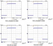
1kHz: Still looks good, with only a slight drop in outout level when loaded. The zobel already has a slight influence, showing some overshoot.
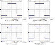
10kHz: now it gets interesting. The unloaded response shows a small amount of ringing with the zobel, but none without. Loaded both has ringing, with the zobel version even more.
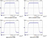
20kHz: very much the same, with the zobel still making things worse. Excessive ringing when loaded.
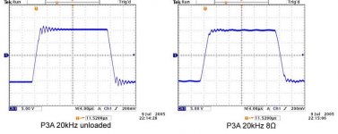
Just for comparison I also measured an ESP P3A, 20kHz square wave loaded and unloaded. The unloaded performs worse than the KSA, but loaded looks better. I guess the next step would be a listening test, and if I have the time, to measure my friend's KSA100 as reference. I think the signs show that C105/106 should be increased. Comments anyone?
Hi guys,
I just finished some measurements on one channel of my test-rig KSA50. I'm building it for a friend who already owns an original KSA100 and KSA200. The entire layout has been copied from the KSA100, including the dimensions, wiring and heatsink & fan assembly. If the result sounds at least as good as the KSA100, it will be rebuilt in a professional copy of the KSA100 chassis.
Specs (per channel) are:
500VA per channel
+-30VDC PSU rails (transformers were already at hand otherwise I would have increased this)
55000uF per rail
4pairs of MJ21194/3 output devices
50W class-A bias
Although I wanted to keep the design as close as possible to the original, some modifications were made.
- twice the number of output devices and heatsink area
- increased PSU capacitance
- MJ21193/4 output transistors rather than MJ15003/4
- DC fuses placed on the busbar for reduced wire length from the PSU
- DC, rather than AC fans with a separate transformer for less injected motor noise
- Top quality components:
- critical resistors are Riken, less critical Holco and the rest Dale
- R127/R128 are 2W 24R Kiwame
- Emitter resistors are 0.5R 5W Mills
- C101 is polystyrene
- C105/106 are 22pF silver mica
- C104/109 are Evox-Rifa 100nF MKP
- C110/C111 are Black Gate Std
- C102/C103 is a single Black Gate 1000uF NX
- All hookup wire is silver coated teflon
- input cable is vD Hul
The 22pF value for C105/106 was chosen fairly arbitrarily. I had some trouble with stabilty though, and the measurements suggest that it is perhaps a little too small. 33pF will probably be a better bet, or even as high as 68pF shouldn't be too bad. The bipolar feedback electrolytic was chosen as 1000uF instead of 470uF simply because I got it on sale, and not any other purpose. I chose to hardwire the emitter resistors directly to the output transistors, and regret it now as it means I cannot measure the bias current on each transistor individually. I used an ammeter in place of the DC fuses to measure the total current (1.8A per rail), as the current consumed by the PCB is only about 5% of the total current. To avoid making a mess I used silicone washers instead of mica & thermal compound. This was a mistake as one transistor is running at least 20degrees hotter than the rest, despite all my best efforts to tighten the screws. Even that one is still less than the KSA100 I examined, but if it wasn't for that I could have easily increased the bias with as much as 50%. On all the rest I can place a finger without burning (just), but the problematic one burns to pain in less than a second - it runs at least 80degrees celsius. Besides the obvious problem of reduced lifespan (I'm not too concerned, the KSA100's MJ15003/4's are running that hot for over 20years without trouble), is there any reason why I should go through all the trouble to desolder & replace the transistor?
The predrivers probably didn't need their small heatsinks, and the driver heatsink was sourced from an old PC PSU. It runs a little hot, but still cooler than the KSA100's - I suspect around 50 degrees.
See the pics and measurements I made. The input signals from the generator were checked, they are all perfect. All deviation is therefore done by the amp and not passed from the input. All measurements were with a 1V amplitude (2V p-p) input signal.
I took a sinewave measurement at 10kHz, unloaded and loaded with an 8ohm load. It looks pretty good on both, no objections there. On the square wave one can learn quite a bit more, comments are welcome. I measured at 20Hz, 1kHz, 10kHz and 20kHz, all loaded and unloaded, with and without a zobel at the output terminals (10ohm & 100nF). It should be noted that squarewave measurements place great demands on a loaded amplifier, much less than sinewaves. I used a 12W 8R2 load resistor and it became scorching hot in less than 5 seconds. I grouped the frequency measurements together in single JPG's (had to compress them a bit) of four measurements each for easy comparison.
20Hz: at that frequency the zobel obviously has no effect. Loaded and unloaded are pretty much identical, with both exhibiting a slight amount of tilt.
1kHz: Still looks good, with only a slight drop in outout level when loaded. The zobel already has a slight influence, showing some overshoot.
10kHz: now it gets interesting. The unloaded response shows a small amount of ringing with the zobel, but none without. Loaded both has ringing, with the zobel version even more.
20kHz: very much the same, with the zobel still making things worse. Excessive ringing when loaded.
Just for comparison I also measured an ESP P3A, 20kHz square wave loaded and unloaded. The unloaded performs worse than the KSA, but loaded looks better. I guess the next step would be a listening test, and if I have the time, to measure my friend's KSA100 as reference. I think the signs show that C105/106 should be increased. Comments anyone?
Attachments
PWatts...
I have no zobel network on mine, and when i did run the square wave tests i had hardly ANY ringing on the rise at all on my (i couldnt' see it on the scope) and the drop off was a bit sharper than yours @ 10khz... I used a 4 ohm dummy load 🙂
To clarify a few things - thanks for the excellent write up explaining everything! Looks excellent too!!!
Also - you said the KSA-100's outputs run @ 80deg? where abouts is that measured from on the TO-3 casing? I'm trying to see how much i can "push" my amp 🙂
Thanks very much
Aaron
- Home
- Amplifiers
- Solid State
- Krell KSA 50 PCB