still4given said:
Hi Anthony,
I don't know what CLC is but I am using CRC.
It uses 0.1R resistors. What size resistors would I need to drop a full 5 volts?
Thanks, Terry
Terry I am a little confused, if you are using 0.1R resistors in a true CRC configuration your volltage drop is neglidgable. Typical values are between 10 and 100 ohms with 50 Watt resistors!
Regards
Anthony
Coulomb said:
Terry I am a little confused, if you are using 0.1R resistors in a true CRC configuration your volltage drop is neglidgable. Typical values are between 10 and 100 ohms with 50 Watt resistors!
Regards
Anthony
The one I use is designed by Rod Elliot.
I calls for 0R1 5W. I guess it is more for clean power than reducing voltage. That is why I asked for the value I would need to drop the 5 volts I need.
Thanks, Terry
still4given said:
The one I use is designed by Rod Elliot.
I calls for 0R1 5W. I guess it is more for clean power than reducing voltage. That is why I asked for the value I would need to drop the 5 volts I need.
Thanks, Terry
Well get your volt meter and check the rail voltage at the front of the CRCRC stage, in the middle and on the output under load and let's see what you got right now.
BTW I would try putting Vin at the front end and taking both outputs off the back end. This way you get maximum filtering for both channels.
Regards
Anthony
Regards
Anthony
hmm
Terry,
are you recieving my emails?
You definitely don't want 10 ohm resistors in the R part of this CRC power supply, with over an amp of idle current the voltage drop would be prodigous, somewhere between 1 and 2 ohms should get the job done. I'd turn it into a RCRC power supply using somewhere between 0r5 or 1r0 as the R's
Stuart
Prolonged high output in low frequencies will kill the rail voltage with high R values in a CRC.
What good is a +400va toroid then?
Without investing in serious capacitor power you'll take the sting from the Krell.
Calculation of a choke PS is not that simple, you dont want to know what a CLC is, Terry, believe me.
What good is a +400va toroid then?
Without investing in serious capacitor power you'll take the sting from the Krell.
Calculation of a choke PS is not that simple, you dont want to know what a CLC is, Terry, believe me.
Re: hmm
Well what do you suggest? .5R is just not enough to load the power supply enough to suppress Current artifacts unless your in the 100Watt Class A range.
BTW I meant 1.0 to 10.0 ohms in an earlier post, I just caught that. oopps
Regards
Anthony
Stuart Easson said:Terry,
are you recieving my emails?
You definitely don't want 10 ohm resistors in the R part of this CRC power supply, with over an amp of idle current the voltage drop would be prodigous, somewhere between 1 and 2 ohms should get the job done. I'd turn it into a RCRC power supply using somewhere between 0r5 or 1r0 as the R's
Stuart
jacco vermeulen said:Prolonged high output in low frequencies will kill the rail voltage with high R values in a CRC.
What good is a +400va toroid then?
Without investing in serious capacitor power you'll take the sting from the Krell.
Well what do you suggest? .5R is just not enough to load the power supply enough to suppress Current artifacts unless your in the 100Watt Class A range.
BTW I meant 1.0 to 10.0 ohms in an earlier post, I just caught that. oopps
Regards
Anthony
I run custom made 800va 30v toroids... One per channel when the guy made them he asked me what regulation i wanted, i said "as good as absolutely possible" there was no extra charge for this, but off load i've got 31.*v, on full load (of my krell channel) it is 30.9v i think! It's VERY well made, i've got 30v ac rails and running 130w full class A into 4ohms.....
Aaron
Aaron
i'm setting bias....
So I fired up the output stage. No smoke. Whew.
Setting the bias, I turn the pot for more and simultaneously reading the wiki about how to do this....and at max setting I only measure .230 V across one .499 ohm emitter resistor. And the heat sink is not getting very warm with no fan running.
I notice as time goes by, the voltage goes up. after 5 min, its at almost .35 V. Things are getting hotter. I hear a soft little clicking from the output stage as I raise and lower bias...hope thats thermal expansion!
after about 5 min I turn it down and let it sit at .2V across the .499 ohm resistor for a few min, then and turn off. Transistors are cool to the touch but the heat sink fins are very hot.
I have 4 pairs of output devices/ch 38V rail, .499 resistors.
so it seems to me that I should be able to set a higher bias level and I'm maxed out. Or am I just getting lower voltages because I'm using .499 resistors rather than .68 as discussed in the wiki? )(obviously my v should be a little lower but I'm not sure of the consequences of the differences I am finding). Good thing I already asked for the exact bias for 50W class A....
Re: Re: Setting the Bias
OK I now see that .2xxx volts across each emitter resistor can = a bunch of power. ooopsie! Hope I didn't blow anything. I had it up to .35 for less than 30 seconds, mostly running it a .2 or .21. whew.
the voltage across the emitter resistors definately go up as time passes. probably .01V per second. But I've not initiated cooling yet. So when I turn the warm amp on it starts at .07 V across the emitter resistors...and in 3 min its up to .18 V. Yes, I've got the bias Q mounted on the same heat sink as the output devices.
So things get quite hot after about 5 min on the heatsinks but the collector metal cans stay kind of lukewarm. Nice. have to try it with a fan next.
K-amps said:
You guys forgot about the trusty Class-A calculator SS I posted several moons ago: Mr. Green Here it is for 8 ohms and 50 watts:
Bias voltage per Emmiter resistor: 221 mv
Speaker ohms 8 ohms
***
Class-A output: Peak 100.4 Watts peak
Class-A output: RMS 50.2 Watts RMS
Efficiency 37.30 %
Max Class-AB RMS 74.00 Watts RMS
and for 70 watts class-A
the voltage across the 0.49 emitter resistors is 261mV up from the 221mV for 50 watts class-A.
Bias voltage per Emmiter resistor: 261 mv
Speaker ohms 8 ohms
Results
Idle bias per device: 0.523 Amps
Class-A output: Peak 140.1 Watts peak
Class-A output: RMS 70.0 Watts RMS
Efficiency 44.05 %
Max Class-AB RMS 74.00 Watts RMS
for 4 ohms, you need double the bias current....
For 50 watts the ER voltage drop would be: 315mV and for 70 watts class-A into 4 ohms the ER voltage drop would be about 369mV across each 0.49 ohm emitter resistor.
K-Amps
OK I now see that .2xxx volts across each emitter resistor can = a bunch of power. ooopsie! Hope I didn't blow anything. I had it up to .35 for less than 30 seconds, mostly running it a .2 or .21. whew.
the voltage across the emitter resistors definately go up as time passes. probably .01V per second. But I've not initiated cooling yet. So when I turn the warm amp on it starts at .07 V across the emitter resistors...and in 3 min its up to .18 V. Yes, I've got the bias Q mounted on the same heat sink as the output devices.
So things get quite hot after about 5 min on the heatsinks but the collector metal cans stay kind of lukewarm. Nice. have to try it with a fan next.
Hi Terry,
if you go to CRC or RCRC with higher resistance then you MUST use very high last C to give back some of the oomph that you will lose due to drooping rail volts. I would guess that +-100mF might just do it.
Instead I recommend that you set the Iq for 10w ClassA and listen for a while checking temps periodically. If you like what you hear then great. You can then set up the high bias pot for 20W classA and listen to that for a while. Which sounds better? Can the temps allow a higher setting if so then adjust it for 30W classA?
Progress from there and remember small steps is what I recommend.
Hi Lgreen,
Don't understand your temperatures.
Metal cans means To3 output stage?
Then the To3s must run hotter than the heatsink by about 10Cdeg to 15Cdeg when in classA.
Have you checked all the Vre for each transistor? Just in case one or two are hogging all the current and running much hotter than the rest.
Output stage
Here is the output stage unconnected to theinput stage. The heat sinks are live and everthing attached to them (save the xistors and clad resistors) is insulated every way it can possibly be-- nylon all over the place.
Andrew- yes it is metal cans as you can see. I've checked a few of the Vre's but it is very difficult to probe all of them and I don't want to short them to + or - VCC with the probe-- so I'm turning things off and on and relocating the probes. so far all the Vre measurements are about the same.
The cases actually feel to be about the same temp as all the other cases, but each appears to be cooler than the heatsink. Weird.
Is it normal for the bias to self-increase as temp goes up? I thought that the bias Q affixed to the output heat sinks would prevent thermal runaway? Then again, i'm only running the thing for 5 min at a time. It might have not settled in yet and I'm not running the fan either.
Here is the output stage unconnected to theinput stage. The heat sinks are live and everthing attached to them (save the xistors and clad resistors) is insulated every way it can possibly be-- nylon all over the place.
An externally hosted image should be here but it was not working when we last tested it.
Andrew- yes it is metal cans as you can see. I've checked a few of the Vre's but it is very difficult to probe all of them and I don't want to short them to + or - VCC with the probe-- so I'm turning things off and on and relocating the probes. so far all the Vre measurements are about the same.
The cases actually feel to be about the same temp as all the other cases, but each appears to be cooler than the heatsink. Weird.
Is it normal for the bias to self-increase as temp goes up? I thought that the bias Q affixed to the output heat sinks would prevent thermal runaway? Then again, i'm only running the thing for 5 min at a time. It might have not settled in yet and I'm not running the fan either.
Hi,
these big heatsink have a large time constant.
You must give the output stage time to stabilise to it's new setting before deciding to make a further adjustment.
Some have said a minimum of 15minutes to assess the temp effects of the last change.
The Vbe multiplier should be measuring the output stage junction temperatures ( all 8 of them) but it can't so you have to give it time to measure some temp change and make it's correction.
The sequence is increase Iq - increase junction Temp (Tj) - increase Tc - increase heatsink temp under To3 - spread heat along backplate - dissipate some heat to air - slower increase in sink fin temp - increase Vbe Tc - increase Vbe Tj - correct Vbias (that took a while) now return to start and wait for Vbe to react again to it's last correction. This is what takes the time and effectively may have to go around the loop 5 or 6 times closing in on the steady state temperatures.
LGreen,
I haven't noticed that much drift in any of the channels that I have running. I want to say the maximum drift with bias set for 50 watts is about .05 to .08, perhaps a tad more from cold to hot. With the bias device mounted on the sink as close to the output devices as you have it, about the samme as mine, you should really be seeing less drift than you are.
Mark
lgreen said:after about 5 min I turn it down and let it sit at .2V across the .499 ohm resistor for a few min, then and turn off. Transistors are cool to the touch but the heat sink fins are very hot.
At 350 mV it was doing 2.8 amp bias, dissipation at 38vdc around 212 watts per channel.
That is 26.5 watts per device, for only a few minutes without a fan on the sink it should not be a problem, clever it is not.
At operating temperature there is a lot of heat in a heatsink, little in the devices.
When you shut down the power the heatsink will cool down slower than the devices, the thermal resistance between them will create a temperature difference.
In effect not long after shutting down the devices will be cooler to the feel than the heatsink.
Why not fully test the amplifier with everything added in class AB before taking it out full ?
When my main boards are finished i'll fully whistle it, and put it on a dummy load first.
(without output devices its an amplifier too, even a serious overkill headphone amplifier)
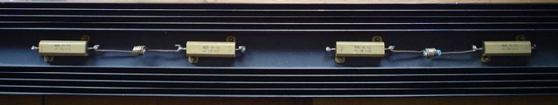
With the outputs connected the Krell will go on the dummy load again in class AB, with only 20-25 mV on the Re's before even considering taking it to full class A operation.
I have no idea how you can post such large pics, even at 50kB the picture of a dummy load i made is rejected.
Attachments
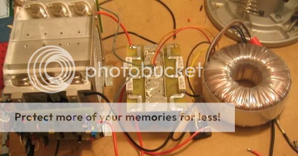
jacco wrote:unwind the secondaries of the toroid to a favorable voltage.
It is easier to make extra windings on top of the isolation and use this as an extra primary winding in series. First make 10 windings and measure the voltage. Then calculate the need.
Loek
It is easier to make extra windings on top of the isolation and use this as an extra primary winding in series. First make 10 windings and measure the voltage. Then calculate the need.
Loek
So... My amp is still running 🙂 Advice?
Well, my amp is still running 100% - just made some changes - now both left/right are "fin to fin" to create a wind tunnel effect... 4 x 8cm panaflow fans running @ 8v, definately quieter than the 6 that were there before! I'm still running high bias (optimised a little - i'm running ~5 ohm speakers!) - about 115-120w @ full class A into 5 ohm... So, both sinks together i'm putting out about 450+w of heat (!!!)....
Obviously the "furthest" bank of transistors are running warm (5 pairs)... I noticed posts previously about the max temp of transistors Tj - what's the "safe" range to keep it in? I'm running +-36Vdc... ~450mv of bias at the moment...(per device)...
Furthest set is hitting about 65 deg on the hottest part of the TO-3 casing (i.e. RIGHT near the dye!)... That's with about 19deg ambient...
Any ideas as to how much more "room" i have for adjustment? Hottest it gets in here is about 30deg ambient.....
Someone help out? 🙂
Thanks
Aaron
P.S. It still sounds great 😀
[edit - "touch" temperature is not an issue at all, my sinks, even at the hottest end (not in direct air flow, i.e. the "ledge" doesn't even reach 50deg]
Re: So... My amp is still running 🙂 Advice?
50% of the SOA, die at 87.5C, same as with AB, gives enough current capability and life expectancy.
Under normal loads without a signal, a class A amplifier experiences the highest dissipation.
With a signal on it the output section may actually cool down : total current through the output devices may be the same, voltagedrop over the devices is lower.
(the Pass rule is to keep dissipation per device under 50 watts)
NUTTTR said:what's the "safe" range to keep it in?
50% of the SOA, die at 87.5C, same as with AB, gives enough current capability and life expectancy.
Under normal loads without a signal, a class A amplifier experiences the highest dissipation.
With a signal on it the output section may actually cool down : total current through the output devices may be the same, voltagedrop over the devices is lower.
(the Pass rule is to keep dissipation per device under 50 watts)
Re: Re: So... My amp is still running 🙂 Advice?
So realistically - i could have all the outputs sitting at 70 deg with ambient 20deg and be very safe...... or go to 75 with 20 ambient, then the hot days (30deg) it will be at about 85deg... so still "safe"... How much hotter is the Tj than the "hottest" part of the case of the TO-3 normally? I measure right at the edge of the die where the top of the to-3 meets the base of the to-3 at that connection... Seems to be the absolute hottest point... Would the Tj (of the dye itself) be much hotter than the case part i'm measuring from? I'm using a K-type probe with a very very small tip, so easy to get accurate readings..>
Aaron
jacco vermeulen said:
50% of the SOA, die at 87.5C, same as with AB, gives enough current capability and life expectancy.
Under normal loads without a signal, a class A amplifier experiences the highest dissipation.
With a signal on it the output section may actually cool down : total current through the output devices may be the same, voltagedrop over the devices is lower.
(the Pass rule is to keep dissipation per device under 50 watts)
So realistically - i could have all the outputs sitting at 70 deg with ambient 20deg and be very safe...... or go to 75 with 20 ambient, then the hot days (30deg) it will be at about 85deg... so still "safe"... How much hotter is the Tj than the "hottest" part of the case of the TO-3 normally? I measure right at the edge of the die where the top of the to-3 meets the base of the to-3 at that connection... Seems to be the absolute hottest point... Would the Tj (of the dye itself) be much hotter than the case part i'm measuring from? I'm using a K-type probe with a very very small tip, so easy to get accurate readings..>
Aaron
jacco vermeulen said:
At 350 mV it was doing 2.8 amp bias, dissipation at 38vdc around 212 watts per channel.
That is 26.5 watts per device, for only a few minutes without a fan on the sink it should not be a problem, clever it is not.
At operating temperature there is a lot of heat in a heatsink, little in the devices.
When you shut down the power the heatsink will cool down slower than the devices, the thermal resistance between them will create a temperature difference.
In effect not long after shutting down the devices will be cooler to the feel than the heatsink.
Why not fully test the amplifier with everything added in class AB before taking it out full ?
When my main boards are finished i'll fully whistle it, and put it on a dummy load first.
(without output devices its an amplifier too, even a serious overkill headphone amplifier)
With the outputs connected the Krell will go on the dummy load again in class AB, with only 20-25 mV on the Re's before even considering taking it to full class A operation.
I have no idea how you can post such large pics, even at 50kB the picture of a dummy load i made is rejected.
1. This is my first time ever adjusting bias, and I wanted to try it quickly without a scope, without input (input was grounded) and without an output load. Saves a lot of time and more importantly space in my garage. I first measured all the voltage points on the input board vs. wiki, things looked good, and connected the output board hoping not to see smoke and I was very happy that it did not blow up on me. I'll try a full setup with input, output, fan, and temp probes later on.
(I see you suggest running the driver boards alone. I already tested the driver boards by themselves (ok 1 of them) by passing sine waves through it, and it appeared to be working. See Post #2514 and the ones preceding it. Not as much testing as you will do I'm sure but it convinced me to go to the next stage).
2. Believe it or not, I'm trying to shrink the pics as much as possible- my home pc must have high resolution or something because when I got to work today that pic was huge! I post pics on my website and link them here-- reason is that I can edit them and changes will be reflected here (side effect is that it avoides the max size limits here). You now see the pic is smaller.
3. The problem of bias being constantly increasing--- perhaps I should measure the voltage across the driver emitter resistors on the driver board-- I think this should be relatively constant and settable by the variable bias resistor. If this V on the driver board emitter resistors is increasing over time then there is a problem with the driver board. Right or not right??
4. I assume temp probes work by passing a voltage through a wire thats resistance changes with temp-- seems to me it would be dangerous to connect such a wire to a live TO-3 or heatsink. Correct or not?
- Home
- Amplifiers
- Solid State
- Krell KSA 50 PCB