Very nice work Ant... funny I seem to remember that design in more than one place... it isnt from your Aleph project is it?
Would those that have signed up on the WIKI to order KSA-50 and power supply boards please e-mail me at the address below. I was going to fish everyones e-mail out of the member list but it turns out that it would take too long and I would have to e-mail each person first, thats way too time consuming. I have the e-mail address at the KSA-50 web site that we will use for this purpose. Then with in a few days we can start to accept payments for them.
Thanks,
Mark
ksa50amp@yahoo.com
Thanks,
Mark
ksa50amp@yahoo.com
K-amps said:Very nice work Ant... funny I seem to remember that design in more than one place... it isnt from your Aleph project is it?
The Aelphs got put into a more traditional shoebox chassis. I like the Krell for this chassis as I can push the amp into A/B mode if it gets to hot for the heatsinks.
Thanks for the feedback guys, this chassis has been around a while, I finished it a year ago and have been trying different amps in it. Hopefully 3rd time is a charm.
Anthony
I froze my buns off walking down Jonge to deliver loek's resistors
If i had known that Stuart i could have send you my heated gloves...
Still waiting for my college who is in Toronto now and picking up my resistors.
Loek
If i had known that Stuart i could have send you my heated gloves...
Still waiting for my college who is in Toronto now and picking up my resistors.
Loek
Coulomb said:Well it is huge, 14" sqaure and 24" tall without the legs.
It has the size of a portable airconditioner, the look of an aircon, the noise of one, cant you make it cool the air in summer months ?

Everyone of your "bodgings" look incredibly professional, whats the plan for the bias of the humongous Krell ?
Hi Terry,
I said take it up in stages measuring semi temps (and heatsinks) as you go.
Have you checked ALL the semis before you took it up to final Iq?
How did you solve the LTP DC offset problem?
Remember the two Iq bias pots, one for low bias maybe when the weather is warm and the other pot for full classA with the jumper/switch to connect for the winter setting. Now you know why it's there.
Full classA monoblocks generally run too hot to touch i.e. heatsink above 40degC, some will run as high as 55degC. Tc will be about 10Cdeg to 15Cdeg above heatsink. Stereo ClassA will run even hotter simply because you start to run out of space for the heatsinks.
You have aggravated this by opting for high PSU rails which will produce (in classA/B) about 80W into 8ohms (severe reactive) and should be able to push 150w into 4ohms (reactive) and maybe 280W into 2ohms (resistive test load only as SOAR now getting close).
You have at least two solutions:-
1. run in two bias mode saving the high bias for cold weather and gentle speaker loads (slightly less Iq).
2. convert your chassis to full monblock and use 6 pairs of output devices for each channel ( which in my humble opinion is what you should have done in the first place- 3 pairs in a stereo chassis with raised Vrail is almost the same as suicide).
An alternative for heatsink problems, which is what i chose for Jens Rasmussen's Leach boards in class A :
Consider multiple fans
Combining fans in series or parallel can sometimes achieve the desired airflow without greatly increasing the system package size or fan diameter.
In series operation, the fans are stacked one upon the other, resulting in an increase of static pressure.
(electronics cooling.com/may96)
(with a second fan on top of the other you can drop temperature of the heatsink by at least 10 C's, lowering bias is a lot cheaper)
Terry, for what all your troubles are worth:
"It is worth noting that it takes a fairly extraordinary loudspeaker to show what's wrong with an FM series Krell, which is without doubt at the top of its class in a way that only the original Krell KSA50 and 100 were able to achieve at the time"
(from a review of the only dynamic loudspeaker i'd die for, Jacques Mahul's Grande Utopia BE)
Re: worst case scenario...
That is very funny, sorry i missed that one first go round !
I am having migraines for over a week now, know what you mean, Stuart, wishing swift recovery.
NH
jacco.
Stuart Easson said:Ooh my head, just back from vegas...
That is very funny, sorry i missed that one first go round !
I am having migraines for over a week now, know what you mean, Stuart, wishing swift recovery.
NH
jacco.
AndrewT said:Hi Terry,
I said take it up in stages measuring semi temps (and heatsinks) as you go.
Have you checked ALL the semis before you took it up to final Iq?
How did you solve the LTP DC offset problem?
Remember the two Iq bias pots, one for low bias maybe when the weather is warm and the other pot for full classA with the jumper/switch to connect for the winter setting. Now you know why it's there.
Full classA monoblocks generally run too hot to touch i.e. heatsink above 40degC, some will run as high as 55degC. Tc will be about 10Cdeg to 15Cdeg above heatsink. Stereo ClassA will run even hotter simply because you start to run out of space for the heatsinks.
You have aggravated this by opting for high PSU rails which will produce (in classA/B) about 80W into 8ohms (severe reactive) and should be able to push 150w into 4ohms (reactive) and maybe 280W into 2ohms (resistive test load only as SOAR now getting close).
You have at least two solutions:-
1. run in two bias mode saving the high bias for cold weather and gentle speaker loads (slightly less Iq).
2. convert your chassis to full monblock and use 6 pairs of output devices for each channel ( which in my humble opinion is what you should have done in the first place- 3 pairs in a stereo chassis with raised Vrail is almost the same as suicide).
Hi Andrew,
First off, I pulled the boards off last night and replaced all of the small transistors and the drivers just to be safe. I also replaced the Zeners. I got data sheets out for all of the transistors I began to measure. I realized that where I had quoted 15.2 V that I was mistaked and it was 15.2 mV. This, I'm hoping is OK because I double and triple checked all of the resistors and I can't seem to get those numbers to match Marks. Like I said, some of my resistors are slightly different than the BOM but within .5 of what was called for.
As far as the 30-0-30 transformer, this was suggested as a good tranny for this amp or I wouldn't have bought it. I don't remember who suggested it, I suppose I could go back and search the posts but it wasn't my idea to go with this. As far as the 3 pair per channel, I was told that the original had 2 pair per channel and that adding one more made sense. I don't have another heatsink like this one to add more outputs so that is out for this amp. Maybe when I build the next one with the new boards I will add more because I have some very large heatsinks set aside for that project. Maybe I'll buy smaller tranformers at that time and use them here and use this one with those boards. I'll have to give that some thought.
Last night I also noticed that I am getting a short to the heatsink with the NPN outputs on one channel. I'm going to pull all of that apart today and see if I can find the problem. I didn't have that problem in the beginning because I was careful to check. It must have happened sometime when I was changing out the outputs for new. Maybe these old carpenters hands are too rough for this hobby. I had better learn to be more delicate.
Blessings, Terry
Hello Terry, you should consider a CRC or CLC power supply configuration, this will drop the rails a few volts and give you a nicer DC supply at the same time. A 12 Gauge 2.0 mH coils should work great for a CLC or CCLC configuration.
Regards
Anthony
Regards
Anthony
jacco vermeulen said:
It has the size of a portable airconditioner, the look of an aircon, the noise of one, cant you make it cool the air in summer months ?
Everyone of your "bodgings" look incredibly professional, whats the plan for the bias of the humongous Krell ?
Thanks Jacco, it's amazing what you can build with materials purchased off eBay. 🙂 🙂
I really do not have a clue what to do with the Bias, I would like to get about 70 watts into 8 ohms with at least 40 or 50 at class A. As I posted earlier with 36VDC rails, 3 pairs per channel and .68R resistors on the outputs, I am not sure what's going to happen.
Regards
Anthony
Coulomb said:Hello Terry, you should consider a CRC or CLC power supply configuration, this will drop the rails a few volts and give you a nicer DC supply at the same time. A 12 Gauge 2.0 mH coils should work great for a CLC or CCLC configuration.
Regards
Anthony
Hi Anthony,
I don't know what CLC is but I am using CRC.
It uses 0.1R resistors. What size resistors would I need to drop a full 5 volts?
Thanks, Terry
still4given said:As far as the 30-0-30 transformer, this was suggested as a good tranny for this amp or I wouldn't have bought it.
If you do not desire the Krell to do 95 watts continuous in 8 ohms an option would be to unwind the secondaries of the toroid to a favorable voltage.
You can unwind it easily to the 27vac needed for 75 watts, that would drop temperature of the heatsink by some 3 degrees.
Think i mentioned the same 6 months ago when you got the Fat Boy from Ebay.
Only problem with unwinding is that you have to take the tape off and retape the toroid afterwards.
Overhere toroids have been used for diy stuff for as long as i can remember, +25 years, some designs even made it obligatory to unwind the PS toroidal transformer.
Terry
CLC = Capacitor / Coil (or choke) / Capacitor.
CRC = Capacitor / Resistor / Capacitor.
Regards
CLC = Capacitor / Coil (or choke) / Capacitor.
CRC = Capacitor / Resistor / Capacitor.
Regards
pinkmouse said:Terry
Mine is running fine on a 30-0-30 traffo if that helps...
Hi Al,
Are you using TO3 outputs?
What value are you using for Re 1-3?
How much drop are you seeing over Re 1?
Is it running very hot?
It was running quite warm initially, so I biased it down to give 25W class A, using 0.68 Ohm outputs. I'll check the exact measurements tonight.
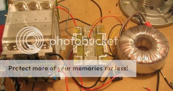
I'm using TO247s at the moment, but If I get chance, I'll connect the pcbs up to the old TO3 stage that the pics showed. That might be tomorrow night though...
I'm using TO247s at the moment, but If I get chance, I'll connect the pcbs up to the old TO3 stage that the pics showed. That might be tomorrow night though...
pinkmouse said:That might be tomorrow night though...
Right after the pub closes ?
Probably not. Beer and volts don't really mix...
Nah, I'll do it before I go to the pub. That way, I can listen to some bangin' tunes when I get home... 🙂
Nah, I'll do it before I go to the pub. That way, I can listen to some bangin' tunes when I get home... 🙂
- Home
- Amplifiers
- Solid State
- Krell KSA 50 PCB