Grounding scheme
Let’s see if this is what most of you will do.
Star ground will be located at the common point formed by both lytics. (common plus and minus rail filters point).
Signal ground will go directly to the PCB and from there returned to the star ground. All other power grounds will be returned to this star.
Star ground will be lifted to chassis by a resistor or thermistor. And of course power ground from mains will be directly attached to chassis.
Would be nice to hear what others are doing or planning.
One of the reasons to ask this is that I have seen projects having a star ground separated from the common point of the PSU, scheme that I never use.
apassgear said:Let’s see if this is what most of you will do.
Tengo los manos arriba, Senor! 😀
Wishing i could write it that clear in few sentences.
Hi,
picture Post 2716 shows a star ground that is electrically excellent.
Note that all the grounds return to the central star ground.
Note also that the central star ground is NOT connected directly to the PSU common. The common star ground is located next to the PSU common but hanging over it with a length of bolt and a nut separating both from each other.
Still4given's layout separates the large charging pulses between the main smoothing caps and the rectifiers from the star and electrically the star ground has a single (very) short connection to PSU common.
Apassgear, is this what you meant when you said "Star ground will be located at the common point formed by both lytics"
One thing not clear is the location of the transformer central tap. It should be direct to PSU common NOT to central star ground.
Comments please.
AndrewT said:Hi,
picture Post 2716 shows a star ground that is electrically excellent.
Note that all the grounds return to the central star ground.
Note also that the central star ground is NOT connected directly to the PSU common. The common star ground is located next to the PSU common but hanging over it with a length of bolt and a nut separating both from each other.
Still4given's layout separates the large charging pulses between the main smoothing caps and the rectifiers from the star and electrically the star ground has a single (very) short connection to PSU common.
Apassgear, is this what you meant when you said "Star ground will be located at the common point formed by both lytics"
One thing not clear is the location of the transformer central tap. It should be direct to PSU common NOT to central star ground.
Comments please.
The reffered picture shows what I would call a star ground located at the common formed by the PSU filter caps. Phisically could not be nearer to the common bus bar.
And yes, the center tap or common from secondary windings would also be conected to the common bus bar but not exactly to the star ground.
In my veiw, when you have a common bus point like this it does not matter if you attach the common from the secondaries directly to the star ground or to the side of the bus bar
One other thing Andrew,
I would not use a steel bolt and nut for the star ground.
A copper bolt is mandatory or at least a bronze one, better still if it has some corrosion protection.
I would not use a steel bolt and nut for the star ground.
A copper bolt is mandatory or at least a bronze one, better still if it has some corrosion protection.
Yep, if you read the application notes from RIFA, (my cap star😉 ), they recommend brass bolts/nuts for that kind of work.A copper bolt is mandatory or at least a bronze one, better still if it has some corrosion protection.
Steen.🙂
AndrewT said:Hi,
picture Post 2716 shows a star ground that is electrically excellent.
Note that all the grounds return to the central star ground.
Note also that the central star ground is NOT connected directly to the PSU common. The common star ground is located next to the PSU common but hanging over it with a length of bolt and a nut separating both from each other.
Still4given's layout separates the large charging pulses between the main smoothing caps and the rectifiers from the star and electrically the star ground has a single (very) short connection to PSU common.
Apassgear, is this what you meant when you said "Star ground will be located at the common point formed by both lytics"
One thing not clear is the location of the transformer central tap. It should be direct to PSU common NOT to central star ground.
Comments please.
Hi Andrew,
The star ground wires are as follows:
Twisted pair (green/blue) are the secondary center tap.
Twisted pair (black) are the transformer primary ground
Three white wires are the - from each of the three PCBs.
Small black wire is from soft-start circuit.
The ground wires for both inputs and speaker outputs land on the PCBs.
The bolt in the star ground has a nut at the bottom where it comes through the base of the chassis to cinch it to the chassis and nuts either side of the copper ground plate. If any of this seems wrong, let me know.
Thanks, Terry
apassgear said:One other thing Andrew,
I would not use a steel bolt and nut for the star ground.
A copper bolt is mandatory or at least a bronze one, better still if it has some corrosion protection.
Huh, I didn't think of using copper or brass. I used a galvanized bolt and nuts. None of my haflers use brass or copper bolts and the screw top filtercaps I own don't have copper or brass screws.
Do you think I will have a problem over time with this bolt?
Thanks, Terry
http://www.evox-rifa.com/europe/technotes_electrolytics.htm
You might want to read some of these papers. Lots of usefull information in there😉
Those guys at RIFA, are surely for long life applications, without faults. I for one, likes to listen to them😉
Steen🙂
You might want to read some of these papers. Lots of usefull information in there😉
Maybe, maybe not. According to the RIFA papers you might!Do you think I will have a problem over time with this bolt?
Those guys at RIFA, are surely for long life applications, without faults. I for one, likes to listen to them😉
Steen🙂
The only time I have ever seen corrosion on capacitor terminal screws was on some moving lights that had been used in a seafront fairground for 6 months...
pinkmouse said:The only time I have ever seen corrosion on capacitor terminal screws was on some moving lights that had been used in a seafront fairground for 6 months...
In which case you will have bigger worries than brass bolts on caps.
still4given said:
Huh, I didn't think of using copper or brass. I used a galvanized bolt and nuts. None of my haflers use brass or copper bolts and the screw top filtercaps I own don't have copper or brass screws.
Do you think I will have a problem over time with this bolt?
Thanks, Terry
We are speaking of quality power grounds for audio. I even see copper and brass been used on good quality mains hardware, guess why.
Steel is not a good conductor!!!! The issue is not corrosion.
I don’t like to see all the current of my amp passing through a steel conductor. It is on the signal path!!! All the PSU is on the signal path. So even the cap screws should be brass.
We take a tremendous amount of care selecting our wires and cables. To end them on a steel connection? Think twice.
K-amps said:
In which case you will have bigger worries than brass bolts on caps.
Well in some parts of Canada it helps to have Brass Nuts! 🙂
Anthony
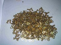
Yep, like these M5's, suitable for the RIFA caps I will be using🙂So even the cap screws should be brass.
Steen.😎
Attachments
Coulomb said:Well in some parts of Canada it helps to have Brass Nuts!
In some parts of Amsterdam they know a lot about nuts and screws.
You think i should ask them for advice ?
My first priority would be a tight nut, choice of material second.
Though i like a bit of Brass.
In some parts of Amsterdam they know a lot about nuts and screws.
Don't know if your power supply connections will benefit from the advice you're gonna get there jacco!😀
Yesterday I ordered the remaining parts from Digi-Key, so if I'm lucky I will have them just before the weekend (if UPS does an effort).
Regards
Dont know too, but in those quaters, a heavy powersupply is a plus😀Don't know if your power supply connections will benefit from the advice you're gonna get there jacco!
Steen.
- Home
- Amplifiers
- Solid State
- Krell KSA 50 PCB