Beautifull setup GeWa,
I see most of us are doing or planning dual monos, as the original. Is anybody considering stereos?
I see most of us are doing or planning dual monos, as the original. Is anybody considering stereos?
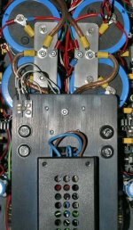
No, it's not. This amp is product of one entusiast from Croatia. He has a lot of time for gluing and soldering a wires between each component on that plexy. I see this before only in the speakers crossovers. Electricly this have some advantages.
Regards
Regards
apassgear said:...I see most of us are doing or planning dual monos, as the original. Is anybody considering stereos? ...
Repute and I got 25 V CT 800VA toroids for 3x KSA-50 (center lower bias) and 2x GC (BrianGT 3875 kit) for the rears.
neychi said:No, it's not. This amp is product of one entusiast from Croatia. He has a lot of time for gluing and soldering a wires between each component on that plexy. I see this before only in the speakers crossovers. Electricly this have some advantages.
Regards
Neychi,
Very interesting, it may be a pain in the *** to replace components....
But in any case I suggest that this type of discussion could be done in a new or appropriate thread since the Krells will have a regular PCB.
You are a very welcomed contributor but rather new to this forums so let me say that we avoid discussing out of topic matters. Already the ML stuff was rather out of topic but accepted since it came when talking about star grounds and bus bar materials.
We will be glad if you join us building the Krells!!! Sign in on the Krell WIKI to get the PCB’s and enjoy the construction and this nice thread.
I’m not a moderator but deem appropriate to make this comment.
Is anybody considering stereos?
I make dubble mono and dubble heatsinks , 4 pairs MJL's per channel for the symmetry.
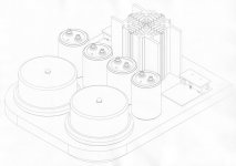
Walter, in post 2775 it seems as you couple the 4 drivertrannies to one heatsink, but in the next (beautifull) drawing i cannot see that.
Loek
I make dubble mono and dubble heatsinks , 4 pairs MJL's per channel for the symmetry.
Walter, in post 2775 it seems as you couple the 4 drivertrannies to one heatsink, but in the next (beautifull) drawing i cannot see that.
Loek
Can you mail the board house for the drill sizes in their standard rack please? I can't find the copy I got from them and choosing a standard size might lead to less grief/expense for the rework.
k, Will e-mail them tonight about that.......
Mark
bus bars ...
I prefer using stainless steel for all my hardware nowadays (including telescopes). Set and forget. It has marginally lesser conductivity than brass or copper, but most importantly will STAY the same long after we are all dead. And few miliohms here or there are easily compensated by using larger bars.
One thing I don't recommend is having the recifiers on bus bars close to main capacitors. In class A amp they get HOT. And I mean HOT ! I was surprised how hot they get. Last thing you want is to heat the caps more than they need. I keep the rectifiers on a separate plate (black anodized aluminium) away from capacitors. Even with fairly large area available (and this plate is connected to the chasis via thick aluminium bars) it is still almost as hot as heathsinks.
Also note how signal star ground connection is offset from the power ground. It is much easier to fight ground loops this way than if you bunch up all of the ground connection together.
You can also see 8 gauge OFC wires (rated 60A) I used to feed the power to the output stage. Important if you want to squeeze those last few amps you need for 1KW+ testing on 1 ohm loads 🙂
Bratislav
Attachments
rabstg said:Repute and I got 25 V CT 800VA toroids for 3x KSA-50 (center lower bias) and 2x GC (BrianGT 3875 kit) for the rears.
I forgot to mention that each channel will have it's own snubbed bridge rectifier and filter caps. The only thing common will be chassis and AC pwr (mains and secondary).
rabstg said:
I forgot to mention that each channel will have it's own snubbed bridge rectifier and filter caps. The only thing common will be chassis and AC pwr (mains and secondary).
... and this is where it gets interesting. It's not always straightforward to connect chassis ground (earth) and two separate signal/power grounds without introducing ground loops.
When you have huge ripple currents pulsing away at big caps' centerpoints ... everything gets complicated that extra bit.
Gentleman
I have a stereoblock in the making- virtually with the identical layout as the original KSA100 using two fan-blocks. Hopefully a picture will posted within a week or two.
Jozua
I have a stereoblock in the making- virtually with the identical layout as the original KSA100 using two fan-blocks. Hopefully a picture will posted within a week or two.
Jozua
Loek
The heatsinks are on the driver PCB's. These are just some ideas, the final design of the amp may look completely different.
How is your project comming along?
Regards
Walter, in post 2775 it seems as you couple the 4 drivertrannies to one heatsink, but in the next (beautifull) drawing i cannot see that.
The heatsinks are on the driver PCB's. These are just some ideas, the final design of the amp may look completely different.
How is your project comming along?
Regards
Attachments
Re: bus bars ...
Nice setup show on the pic.
For me, I may stress, the theoretical concept of a bus bar is one that has equal potential at any point, so installing two point star ground over it is irrelevant or the same as having only one.
If I want equal potential at any point on the bus bar, cross section and material is of prime importance. So copper (or silver if I could afford it) is my first choice always. As second choice, alu or brass, but never any kind of steel which is considered a bad conductor. Of course stainless could be the material of choice when you only consider corrosion and not electrical properties.
My two cents.
Bratislav said:I prefer using stainless steel for all my hardware nowadays (including telescopes). Set and forget. It has marginally lesser conductivity than brass or copper, but most importantly will STAY the same long after we are all dead. And few miliohms here or there are easily compensated by using larger bars.
One thing I don't recommend is having the recifiers on bus bars close to main capacitors. In class A amp they get HOT. And I mean HOT ! I was surprised how hot they get. Last thing you want is to heat the caps more than they need. I keep the rectifiers on a separate plate (black anodized aluminium) away from capacitors. Even with fairly large area available (and this plate is connected to the chasis via thick aluminium bars) it is still almost as hot as heathsinks.
Also note how signal star ground connection is offset from the power ground. It is much easier to fight ground loops this way than if you bunch up all of the ground connection together.
You can also see 8 gauge OFC wires (rated 60A) I used to feed the power to the output stage. Important if you want to squeeze those last few amps you need for 1KW+ testing on 1 ohm loads 🙂
Nice setup show on the pic.
For me, I may stress, the theoretical concept of a bus bar is one that has equal potential at any point, so installing two point star ground over it is irrelevant or the same as having only one.
If I want equal potential at any point on the bus bar, cross section and material is of prime importance. So copper (or silver if I could afford it) is my first choice always. As second choice, alu or brass, but never any kind of steel which is considered a bad conductor. Of course stainless could be the material of choice when you only consider corrosion and not electrical properties.
My two cents.
Jozua said:
I have a stereoblock in the making- virtually with the identical layout as the original KSA100 using two fan-blocks. Hopefully a picture will posted within a week or two.
Will love to see those pics. Please post them.
Sorry Tony, and everybody else
I was little bit out of line
I'm just gather all parts for Krell, and start soldering.
Btw, I have two extra Jan's board with fixed layout (for trimpots), so if someone is interested...
Regards
I was little bit out of line
I'm just gather all parts for Krell, and start soldering.
Btw, I have two extra Jan's board with fixed layout (for trimpots), so if someone is interested...
Regards
Hi,
Walter, how big heatsinks for drivers do you have in mind? I have 4 C/W for every driver, would they be sufficient?
Cheers
Walter, how big heatsinks for drivers do you have in mind? I have 4 C/W for every driver, would they be sufficient?
Cheers
Hi neychi
Mine is a custom made heatsink. It's milled out of a solid piece of aluminium. All walls are 3mm thick and the length is 75mm.
From what I gathered here is that all transistors should be mounted on the same heatsink for better tracking.
This is a question for the expert cloners. (Mark, Al, K-amps where are you.....)
Cheers
Attachments
thermal tracking...
The only transistor that has to thermally track anything much is q111. It has to be at a temp which is going to change in the same way as the output stage. This can be achieved by bolting it to the same heatsink as the outputs, or by bolting it to the heatsink for the drivers, whichever is most convenient. There is no specific reason why the drivers need to be on any heatsink with anything else....
If the driver heatsink option is used, the heatsink should be chosen to give temps that approx. track the output stage. It would be detrimental to the whole thermal compensation process to put q111 on an overly large driver heatsink that keeps it cool, if the outputs are cooking...
Stuart
Hi Neychi,
re offer in post 2795; Is this the board that Stuart, Mark & others are building just now?
The Vbe multiplier (q111) must be on the output heatsink.
The drivers can be mounted on separate heatsink/s, but the heatsink/s should be sized so that the driver case temp (Tc) is similar to the output case temp.
You can predict this if you know the driver Iq, +-Vrails, Rth mounting, Rthsink, Tambient (internal).
Here is another suggestion for the Wiki; how to size the driver heatsinks.
- Home
- Amplifiers
- Solid State
- Krell KSA 50 PCB