The rest of the bits arrived this morning! 😀
I'll see about getting something up and running after work tonight. I can't wait!
I'll see about getting something up and running after work tonight. I can't wait!
Hey guys,
Well I picked up some 10w 27k resistors and hooked up my 55-0-55 transformer through a bridge to the two caps. Measuring across the resistors I initially saw 42v drop. After about 1 1/2 hours it was down to a 3v drop and the caps were holding 90VDC with 0VAC. Looks like they've recovered. 😎
I wish I had read this 2 weeks ago, would've saved me $50.
It makes me wonder how many of the other caps I've thrown away may have been able to be saved.
Oh well, they say you have to pay to learn. 😀
Blessings, Terry
I think that Pinkmouse is soldering his *** of for the moment because he's still not online.😀
Not quite, got stuck at work, and I just got in. Need to eat before I do anything.
But I do have tomorrow morning off in return, so watch this space!
But I do have tomorrow morning off in return, so watch this space!
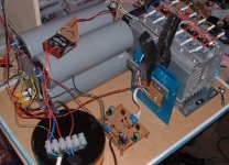
Well, I just discovered the obvious. With 2f worth of caps, you need a slow start circuit!
Time to replace the bridge for a bigger one... 🙂
Time to replace the bridge for a bigger one... 🙂
pinkmouse said:Well, I just discovered the obvious. With 2f worth of caps, you need a slow start circuit!
Time to replace the bridge for a bigger one... 🙂
Wow! That's a lot of capacitance!
What you're planning to use for the slow start
circuit? Do you think something simple like a thermistor
on the transformer primary will work?
Cheers,
Dennis
Hi,
your 2f had me thinking this was a french (Canadian ) version of 2 cents worth i.e. cheap. But the penny dropped finally & realised 2 Farads (2F).
So all those caps I bought for 6amps (only 1.2F) leave me well short if your solution proves to be right.
Keep us posted.
your 2f had me thinking this was a french (Canadian ) version of 2 cents worth i.e. cheap. But the penny dropped finally & realised 2 Farads (2F).
So all those caps I bought for 6amps (only 1.2F) leave me well short if your solution proves to be right.
Keep us posted.
I don't remeber if it was Mark or Stuart, but one of them said that the requirement appeared to be 58,000 or 68,000uF per channel on each rail.
The 2F was just an experiment, I will actually be using two 58,000uF per rail.
I popped out from work today and got a new bridge, and a couple of big thermistors to wire in tonight when I get home.
I now know the board will work correctly, as I have let the magic smoke out of that bridge rectifier, so the gods of diy have had their sacrifice...🙂
I popped out from work today and got a new bridge, and a couple of big thermistors to wire in tonight when I get home.
I now know the board will work correctly, as I have let the magic smoke out of that bridge rectifier, so the gods of diy have had their sacrifice...🙂
K-amps said:I think the KSA50's had 40,000mF IIRC.
Per rail, per channel, so four caps in total of course. 😉
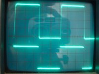
testing the input board
Got the input board assembled, any recommendations on how to test this thing? What to look for? post on wiki?
Got the input board assembled, any recommendations on how to test this thing? What to look for? post on wiki?
one more
one more question-
8 output devices (4 MJ21193/94 pairs) per channel at 38 VDC, emitter resistors are 1% 10W metal clad dale at .499 ohms, no base resistors or protection circ.
What is my class A power and any other issues?
I am using these resistors because I have enough of them and because my heat sinks are already threaded to mount them; but I could select and mount others if it were necessary though its far easier to use what I have.
thanks
output power is...
...about 80watts RMS for a 38v rail, but the percentage which is class A is dependant on the idle current you have dialed in for the output stage...k-amps has a spreadsheet that allows more exact values to be calculated for the various parameters you've supplied.
With the 'stock' 1.9 amps you get about 55w that are class A, the rest being class B, since one half or the other of the output stage is off...more idle current equals more class A output and more heat...
If you want to drive 4 ohm loads to the Class A theoretical max for a 38v rail, you would need 4 or more amps of idle current, and huge heatsinks...obviously krell decided against this course of action, they supply 55w class A into 8 ohms, anything more into lower impedance loads is class B...
I think the spreadsheet is linked from the build sheet wiki page, if not paerhaps someone that knows how can attach it...it would be a handy tool for those deciding on params for their build...
Stuart
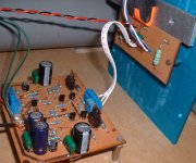
Ok, the main problem I have is that I seem to have a short somewhere in the output module. This doesn't register on the low voltage of the DMM I used to check it, but the higher voltage from the rails is obviously breaking through somehow. I might just knock something temporary up with four devices for testing so we can get the GB underway.
Here's a closup of the pcbs for those that are interested. 😉
Here's a closup of the pcbs for those that are interested. 😉
Attachments
Re: one more
What is the voltage drop across the 0.49 resistors? Do you have a number or do you want to know what the drop should be for 50 watts class-A?
If it is the latter, any of the emmitter resistors should have exactly 216.5mV across them to give you 50 watts pure class-A.
The 4 ohm class-A (100 watts class-A) is 433mV (3.5amps) and at 4 ohm 50 watts class-A your bias should be: 306.4mV (2.5A).
K-
lgreen said:one more question-
8 output devices (4 MJ21193/94 pairs) per channel at 38 VDC, emitter resistors are 1% 10W metal clad dale at .499 ohms, no base resistors or protection circ.
What is my class A power and any other issues?
I am using these resistors because I have enough of them and because my heat sinks are already threaded to mount them; but I could select and mount others if it were necessary though its far easier to use what I have.
thanks
What is the voltage drop across the 0.49 resistors? Do you have a number or do you want to know what the drop should be for 50 watts class-A?
If it is the latter, any of the emmitter resistors should have exactly 216.5mV across them to give you 50 watts pure class-A.
The 4 ohm class-A (100 watts class-A) is 433mV (3.5amps) and at 4 ohm 50 watts class-A your bias should be: 306.4mV (2.5A).
K-
- Home
- Amplifiers
- Solid State
- Krell KSA 50 PCB