Re: It Works!!!!

/outta here........ 🙂
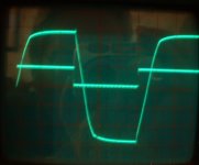
Hey!! There's a reflection of some goofy guy holding a camera!!pinkmouse said:1KHz square wave. Top trace output, bottom trace source, (x10). 😀😀😀
/outta here........ 🙂
Right, before I go out...
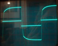
Emitter resistors on Q107/8 increased to 330R as my rails were a bit high, and they were running very hot, but I'll swap back later.
Input -10KHz square wave, 0.75V P2P.
Output -12V P2P
First pic - 330pF on Q107/108. Hmmm. If that's what you put in, rip 'em out...
Emitter resistors on Q107/8 increased to 330R as my rails were a bit high, and they were running very hot, but I'll swap back later.
Input -10KHz square wave, 0.75V P2P.
Output -12V P2P
First pic - 330pF on Q107/108. Hmmm. If that's what you put in, rip 'em out...
Attachments
I must be haunted! That goofy guy is in all my pics, yet I'm sure I was in the house alone! 😉
Coulomb said:Hey Pinky, that's quite a mop you got there, you need a haircut. 🙂
Anthony
Anthony,
His nostril hairs are his own business....
K-amps said:His nostril hairs are his own business....
At least none of you have slagged off my ancient 'scope yet!
al/was holding the camera at waist level...
pinkmouse said:
al/was holding the camera at waist level...
I don't think anyone is going to touch that one.... Literally... 🙂
pinkmouse said:
At least none of you have slagged off my ancient 'scope yet!
al/was holding the camera at waist level...
Well in that case Anthony might be referring to some other mop.... 🙄 What was it Anthony?
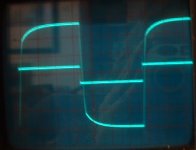
With 33pf i don't remember my scope readout looking like that!!!!
Hmmmm....... I don't have a signal generator (nor does my scope) but the input was the same as the output just more swing...
I never saw it looking that bad!
Aaron
Hmmmm....... I don't have a signal generator (nor does my scope) but the input was the same as the output just more swing...
I never saw it looking that bad!
Aaron
First pic - 330pF on Q107/108. Hmmm. If that's what you put in, rip 'em out...
With 33pf i don't remember my scope readout looking like that!!!!
This type of information should be put in the WIKI so that subsequent builders can use the info gained in your testing, the schematic says 330 pF. I know you probably haven't had time yet, but remember its a pain to read through all these posts to tweak the component values. Just trying to encourage wiki building. wiki
I don't have a signal generator (nor does my scope) but the input was the same as the output just more swing...
I do have signal generator but figured many of us DIYers don't. For this reason I've put some test tones on my web site for dowloading by anyone. You can burn them to cd or tape then presto! you've got a signal generator. Click the www link below.
To Al : Value of C 105/106 must be as possible low, 'cos this compensation reduce OLG at high frequency, which lead to rising of distortion. Try to get there lowest value, by which amp will be still stable.
Ok guys, I'm just back from the pub,(  ) so no more testing tonight!
Pavel - I think I will try using the old twisted insulated wire method to see if I can get something of around 5pF to try.
Aaron - that was a 10KHz square wave, a difficult test for just about any amp. Normal sine waves or music won't show anywhere near that kind of distortion. But if you get chance to put a scope on yours, I would be interested to see your results.
Lgreen - I'll have a go at adding some stuff to the wiki tomorrow. Good idea about the test tones, but what does a 10KHz square wave look like from a cd?
All - So far I have been using MPSA42/92 throughout, but I might give the original spec-ced 2SC2240 and 2SA970 a go and see how they work. If they perform better I will have to tweek the pcb as the pinout is different, so it would be handy to know now! 🙂
) so no more testing tonight! Pavel - I think I will try using the old twisted insulated wire method to see if I can get something of around 5pF to try.
Aaron - that was a 10KHz square wave, a difficult test for just about any amp. Normal sine waves or music won't show anywhere near that kind of distortion. But if you get chance to put a scope on yours, I would be interested to see your results.
Lgreen - I'll have a go at adding some stuff to the wiki tomorrow. Good idea about the test tones, but what does a 10KHz square wave look like from a cd?
All - So far I have been using MPSA42/92 throughout, but I might give the original spec-ced 2SC2240 and 2SA970 a go and see how they work. If they perform better I will have to tweek the pcb as the pinout is different, so it would be handy to know now! 🙂
Square Wave
Thanks, its much appreciated!
The 10 KHz square wave is so high in freq, that recording to 44.1 KHz sampling rate turns out not to come out very good at all. You are limited by sampling rate and there is a lot of ringing. For example, I've got a 1KHz square wave for download. Here is a link to the 1KHz square wave data. As you see, even at 1KHz you have a lot of ringing.
Lgreen - I'll have a go at adding some stuff to the wiki tomorrow. Good idea about the test tones, but what does a 10KHz square wave look like from a cd?
Thanks, its much appreciated!
The 10 KHz square wave is so high in freq, that recording to 44.1 KHz sampling rate turns out not to come out very good at all. You are limited by sampling rate and there is a lot of ringing. For example, I've got a 1KHz square wave for download. Here is a link to the 1KHz square wave data. As you see, even at 1KHz you have a lot of ringing.
Ringing.. Hello, Hello is anyone there? ...That's funny I could have swore I heard the phone ringing...Who was it darling? Oh just some "Square" I suppose.
🙂
🙂
- Home
- Amplifiers
- Solid State
- Krell KSA 50 PCB