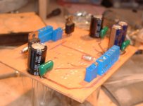
Right next to the trimmers you see two rectangles with the notation "Low" underneath. You can place a jumper or the wires from a switch if you want.
Stuart beat me to this one.
Stuart beat me to this one.
I am thinking of possibly using the low bias setting for a sort of "standby state" to keep the amp warm.
Although I don't think so, does anybody know if switching between low bias to high bias and vice-versa will cause a "pop"?
Also, what are people doing for "soft starting"? I only saw a couple posts but no real details.
Thanks,
Rep
Although I don't think so, does anybody know if switching between low bias to high bias and vice-versa will cause a "pop"?
Also, what are people doing for "soft starting"? I only saw a couple posts but no real details.
Thanks,
Rep
I do ask that anyone who edits the Wiki follow some sort of organization.
Don't just post randomly... Edit the index to add chapters if needed and post like topics together in those chapters.
Don't just post randomly... Edit the index to add chapters if needed and post like topics together in those chapters.
exactly what it's for...
The fact that the KSA50 is a class AB amp means you will get the full power you 'paid for' whether it is switched to high or low bias, but I don't know if anyone has tested whether there is an audible pop when it is switched...not for the 'main' speakers...
NUTTR found the amp sounded Ok with lowish bias but IIRC it sounded better at high bias...
Stuart
More Wiki Edits
I have reformatted the chapters, links and such and edited questions/ answers.
I would recommend that people post construction related facts in the wiki as questions are answered the info can be shortened so that in the end the wiki has everything necessary and answers all common questions.
Thanks for the answers so far, but as you see i'm still confused on the 2 bias options.
w/r to soft start, i've finally got mine working, thanks to GregoryD. See this thread. I'll post a link in the wiki.
I might have some extra boards and also might possibly consider selling them; I've already corrected the problem on all 8 of my boards (I had to buy a min. order to have the boards made).
I have reformatted the chapters, links and such and edited questions/ answers.
I would recommend that people post construction related facts in the wiki as questions are answered the info can be shortened so that in the end the wiki has everything necessary and answers all common questions.
Thanks for the answers so far, but as you see i'm still confused on the 2 bias options.
Also, what are people doing for "soft starting"? I only saw a couple posts but no real details.
w/r to soft start, i've finally got mine working, thanks to GregoryD. See this thread. I'll post a link in the wiki.
I might have some extra boards and also might possibly consider selling them; I've already corrected the problem on all 8 of my boards (I had to buy a min. order to have the boards made).
The original PCB's work just fine....
I've not had a problem with construction, dale resistors, etc, etc... Only problem i really had was the heat from the drivers, fixed easier than suspected by mounting on the main heatsink, it's a bit tricky, but isn't that half the fun? Overall still looks pretty professional (well, doesn't look amatuer...) so i'm happy!
Aaron
I am going to use the softstarters from Per-Anders. Just waiting for components for the boards.
I added a few comments to the Wiki based on my experience so far. Anyone please feel free to edit or delete it if it is deemed un-necessary. I added a few voltage rail omments and the paragraph on heatsinking.
Anyone else get theirs going yet?
Al,
I might be willing to take on the PCB group buy fomr over here. I owuld need someone to set up a WIki for it though. I will also talk to Brian GT and see if he'd like to add this baord to his web site..... Will report back on this when I hear from him.
Mark
Anyone else get theirs going yet?
Al,
I might be willing to take on the PCB group buy fomr over here. I owuld need someone to set up a WIki for it though. I will also talk to Brian GT and see if he'd like to add this baord to his web site..... Will report back on this when I hear from him.
Mark
wiki
Great, thanks, this will be useful to me, I've put together most of the 2 channel boards and got the soft start board working, I'm waiting for my Xformers. It will be months till I have time to assemble the whole unit, but I like to read up on everyone else's experiences while I wait for time in the garage.
For some reason I disassembled my Gainclone and redid it with the BrianGT 3886 snubber boards. For a kit type of project this took me forever, and, as usual, I blew up a bunch of components (this time some of the bizillion power supply diodes). Nothing in DIY is easy, but worse yet it stalled me on the Krell project. At least not I've got a DIY amp to listen to at the office.
Anyway, back to the Krell, what would be helpful to me is if those of you who have this working post a schematic with DC voltages superimposed on the junctions so others can verify that everything is as it should be.
I added a few comments to the Wiki based on my experience so far. Anyone please feel free to edit or delete it if it is deemed un-necessary. I added a few voltage rail omments and the paragraph on heatsinking.
Great, thanks, this will be useful to me, I've put together most of the 2 channel boards and got the soft start board working, I'm waiting for my Xformers. It will be months till I have time to assemble the whole unit, but I like to read up on everyone else's experiences while I wait for time in the garage.
For some reason I disassembled my Gainclone and redid it with the BrianGT 3886 snubber boards. For a kit type of project this took me forever, and, as usual, I blew up a bunch of components (this time some of the bizillion power supply diodes). Nothing in DIY is easy, but worse yet it stalled me on the Krell project. At least not I've got a DIY amp to listen to at the office.
Anyway, back to the Krell, what would be helpful to me is if those of you who have this working post a schematic with DC voltages superimposed on the junctions so others can verify that everything is as it should be.
Mark A. Gulbrandsen said:I might be willing to take on the PCB group buy fomr over here. I owuld need someone to set up a WIki for it though. I will also talk to Brian GT and see if he'd like to add this baord to his web site..... Will report back on this when I hear from him.
I am willing to work with Mark to make him an order page and help him setup something up for a GB. I have been out of town for the last 4 days on a business trip, and have to catch up on a few other things, but I will talk to Mark about this soon.
--
Brian
Thanks a lot guys. As soon as I confirm that the prototype works as planned I will get the files posted. I'm still waiting on a few bits that are back ordered, they should be with me for the weekend.
There will be but we have to accomplish two things first....
1. Al need to comfirm that the prototype PCb works
2. Get quotes for the PCB's to list prices on the Wiki
Thanks Brian, I will take you up on that very soon!!
If I handle the group buy over here the boards will need to be manufactured over here. More than likely from the same place (Advanced Circuits) Brian GT gets the Aleph boards made, or from the place that made the first run of KSA-50 boards from Jan's file.
Both of these board houses do VERY good work so I'd list the least expensive route to go with on the WIKI. Check back soon!
Mark
By the way guys, I was just looking at the sheer number of posts on this thread and it seems our thread has the highest number of replies in the active threads and growing.  (Next highest is a good 200 posts less than ours).
Once again thanks to all who contributed.
Special thanks to Bra for coming up with the schematic and thread, Jan and Pavel for the PCB design, Troy for setting up the group buy, Pinky for a new approach to KSA-50 PCB design, Stuart for his expert advice and Mark for his selfless indulgence. If I missed anyone out please feel free to sock it up to me. 😉
Kudos!
(This is not over yet 😀 )
(Next highest is a good 200 posts less than ours).Once again thanks to all who contributed.
Special thanks to Bra for coming up with the schematic and thread, Jan and Pavel for the PCB design, Troy for setting up the group buy, Pinky for a new approach to KSA-50 PCB design, Stuart for his expert advice and Mark for his selfless indulgence. If I missed anyone out please feel free to sock it up to me. 😉
Kudos!
(This is not over yet 😀 )
bias pots
In the "pinkmouse design" there is one biaspot.
Anybody in for a second?
In the "Jan" design there are two holes to switch for normal/low bias position.
If you connect these 2 is the normal(high) bias situation.
So with only pot R126 in circuit is low bias position.
Loek
In the "pinkmouse design" there is one biaspot.
Anybody in for a second?
In the "Jan" design there are two holes to switch for normal/low bias position.
If you connect these 2 is the normal(high) bias situation.
So with only pot R126 in circuit is low bias position.
Loek
In the "pinkmouse design" there is one biaspot.
PLEASE... No extra stuff on these boards please. If you want a second bias pot just hang it right on the bias switch. BTW.... use a make before break switch or you may throw the amp into max current draw if you use a switch that goes open before it makes the next contact. The equivelent of an open bias transistor..... Ouch! Also, it is all the extra and really un-necessary stuff on Jan's board that has confused some people interested in building this amp.
If you want current limmiting tack it together on a perf board and try it... Its not necessarily a good thing and can also damage to speakers. I would prefer if we could just stick to the "stock" KSA-50 circuit this time around as per Al's design...... Al's design is very well done.
Thanks,
Mark
Re: bias pots
As Mark replied above, with the addition that there isn't any room! 😉
loek said:In the "pinkmouse design" there is one biaspot.
As Mark replied above, with the addition that there isn't any room! 😉
- Home
- Amplifiers
- Solid State
- Krell KSA 50 PCB