These low value resistors aren't in amps for suppresing of bypass spikes, but for suppresing of ground loops, which is different problem.
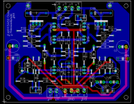
Ok, here is the schematic I'm using.
I'll lay out the grounds in any feasible way, what do you suggest?
If we split them then to my thinking, R102 and C101 should connect to a signal ground, and all the others are relatively higher current and so should be starred seperately.
Thoughts?
:edit: I'm thinking of 100 or 470uf for C1 and C2, mostly 'cos I have those in 50V in my bits box.
Attachments
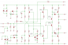
Connect together grounds of C 1 - 4 : it will be so called " power ground " and lead it by separated wire to middle of main PS. All other grounds are " signal " and they must be lead by second wire.
Yes, this is correct, but make there input ground doubled - one for connection with PS and second for connection with input connector ( RCA cinch ) 😉 .
Yes, this is correct, but make there input ground doubled - one for connection with PS and second for connection with input connector ( RCA cinch ) .
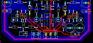
Yes, I absolutely agree...... I think the board design is just about there.... Those seperate grounds are a VERY good idea. I may go back and do the same to my Aleph 2's... I can cut the traces to the zener bypasses and run a seperate wire to the common ground buss!!
Excellent suggestions and good work guys!!!
Mark
Ground plane
... was used in KMA 200 (with lots of polypropilene decoupling caps). The only noise I get is faint thermionic hiss that won't even register on my DMM. Considering how loud this amp can get when asked, I have no doubt its S/N ratio is WELL above 100dB. In any case, as soon as I connect anything to it, the hiss gets louder (the Audio research LS7, which is specified 102dB lifts the residual noise floor a LOT compared to the power amp when switched on/de-muted). I know, it gets amplified 26x, but still.
I wouldn't get too obsessed with grounding (one just needs to be careful). Even if you reach 130dB S/N, it gets negated the very moment you connect anything upstream. And you DO intend to connect something to amp's input, don't you ? ... 🙂
If you have volume regulator based on low impedance T or Pi divider, which is connected directly on input of power amp, you can to get very excelent SNR also by normal listening levels. 😉

Excellent job, you ought to be doing this professionally! Let me know when you order some and I'll Pay Pal some $$ to you for a dozen or so boards. Perhaps a group buy may be in order for this version too.
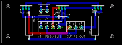
I think that if you just make a second smaller board for the driver stage that you'd be all done with it. I feel it would be best to keep them seperate from the output stage. There may be some that just don't have much space available on their air tunnels (the original KSA-50 or 100 didn't) to mount them. This would allow mounting the driver board in any convenient location near the output stage as Krell did with the KSA-80 driver board, or just attach the drivers to the chassis some place. This would also allow you to expand to a higher power version by also adding more driver boards to each bank of outputs as in the KSA-100.
Added after seeing driver board.....
Can you go back to the main board again and add two more V+/- pads in front of C-105,6, just extend the rails foil up to in front of those caps? This would allow for straight over jumping of the V+/- rails to the driver board. Its best to keep the pads lined up pad for pad a straight jump over from one to the other. Makes wiring alot easier, if this is possible. Also, need to have the backs of the devices right at the edge of the pcb so there is no pcb edge in the way when attaching it to a flat back sink. Multiple pads for V+/- are also a good idea to have there. This could actually end up being the rail tie points.
Mark
Mark, I saw your first post but missed the edit. Probably a good thing as I have had 24 hours to chill, and now I'm not going to cry! 🙂
Power pads, no problems. Is it worth sticking optional pads in for another set of rail caps?
As for the position of the transistors, I was thinking of bottom mounting them, then bending them parallel with the pcb. It just gives a bit more room to run power rails, y'know?
Power pads, no problems. Is it worth sticking optional pads in for another set of rail caps?
As for the position of the transistors, I was thinking of bottom mounting them, then bending them parallel with the pcb. It just gives a bit more room to run power rails, y'know?
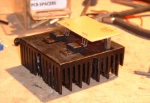
To Al : It's OK, but by my opinionis this heatsink is redundant for this application - power dissipation at drivers isn't so high.
What do you mean by " normal " heatsink for TO 220 ? If you mean typical " small " one, it will be thruth. But I was meaning some square metal sheet cca 2.5 mm thick. Think logical : if you will have output transistors with beta cca 50, you will need only 1 W for driwing ( for output 50 W ) and it is not so much.
You know, all is relative - if you take in your arms pot with 50 °C warm watter, you can't hold it, but all will be OK - semiconductors can work by much higher temperature, remember at some 3 GHz processor. 😎 Good night 🙂
- Home
- Amplifiers
- Solid State
- Krell KSA 50 PCB