I think it is a pitty that most designers of PCB's make single pads on PCB's to connect all the leads, like power leades, output leads and others.
Wire connections on PCB's are i.m.o. never a good and proffesional solution.
Why not make pads on the PCB's were you can solder par example wago levers for all the connections?
I.m.o. much more proffesional.
Wire connections on PCB's are i.m.o. never a good and proffesional solution.
Why not make pads on the PCB's were you can solder par example wago levers for all the connections?
I.m.o. much more proffesional.
To wim : It is thing, which make an amateur to professional 😉 - amateur never think about repairing 😀 and about easy dismantling. But not all are the same - look at work of Per - Anders and ( my ) 😎 .
To Upupa Epops:
I bought some boards from Per -Anders (softstarters), and i know he is doing the way i like.
I bought some boards from Per -Anders (softstarters), and i know he is doing the way i like.
Mark.
I will move the trimmer, as you suggested, but axial caps take up loads of real estate on a board, and I'm not sure I have it to spare!
Wim/Pavel
I know what you mean about connectors making a much more professional looking board, and being easier to service. I was thinking of using a pc style pin connector and ribbon cable to connect to the driver board. If I rework things a little I might be able to get screw terminals for the power as well. I'm also thinking about having the ability to fit a couple of Pavel's favourite rail decoupling caps as an optional extra.
pinkmouse said:Mark.
I will move the trimmer, as you suggested, but axial caps take up loads of real estate on a board, and I'm not sure I have it to spare!
Wim/Pavel
I know what you mean about connectors making a much more professional looking board, and being easier to service. I was thinking of using a pc style pin connector and ribbon cable to connect to the driver board. If I rework things a little I might be able to get screw terminals for the power as well. I'm also thinking about having the ability to fit a couple of Pavel's favourite rail decoupling caps as an optional extra.
Pinky, That reminds me of the famous Pioneer SX-1280/ 1980 receivers that go for big bucks even today. They suffer from corroded terminals not much unlike what you are trying to do. PC's are not designed to survive more than 5 years... basically how long do you want to keep your KSA-50?
😀
K-amps said:They suffer from corroded terminals not much unlike what you are trying to do... basically how long do you want to keep your KSA-50?
You don't have to use the connectors if you don't want to, you can still solder to the pads. It's just another option. 🙂
I know I won't; I was just sharing some experiences with you... I wouldnt want a friend to do it either. 🙂
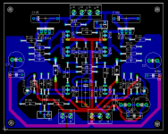
No output ground on this Pavel, this is just a sub-board for the input stage. There are two other boards, one for the bias and driver transistors that mounts on the main heatsink, and separate output boards. These last two might be combined into one, maybe scored, maybe not!
If you have here one common ground connected to ground of main supply, in signal will be spikes from bypass elyts.
So are ground planes any use at all in analogue electronics? Should I just run a GP connected to the signal input ground and star all the bypass caps to the central chassis star?
BTW Pavel, you are a great help. 😎 Thanks for all the advice!
BTW Pavel, you are a great help. 😎 Thanks for all the advice!
Al, where have you output ground ?
The KSA-50 output ground is actually tied to the power supply capacitors ground bar/buss.
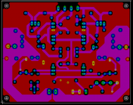
I don't know what he is talking about... spikes from elyts???? I never had any trouble with non-ground plane boards in audio amps, we're not dealing with RF equipment here.. The star grounding scheme seemed to be a good idea actually and it is very symetrical... now if one could make all those ground traces the exact same length... that would be the cats meow but asking for too much. Thats what they do in the Halcro amps, I was told.
The main thing I dislike about ground planes is that it can be very difficult to remove parts, especially TO-220 devices. I even have a professional vacuum de-soldering tool and its still a pain if you have a plane. The only possible advantage might be a bit quieter amp of you live in a high level RF area. Mine is inaudible with my ear right next to the tweeter,basically dead quiet and Salt Lake City is a very concentrated RF zone!!!
Mark
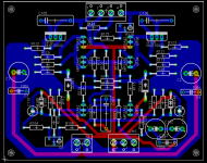
Mark, if you have commom ground wire from elyts + input ground, in this wire you have inrush spikes. These spikes comes across shunt resistor to input, you must remember, that ground wire haven't zero resistance. " Bypass " ground and input ground you must lead to the middle of PS by two separated wires.
I won't disagree with that possibility but in the past it has never been a problem in any projects I have built. Very few commercial amps have a seperate ground for the bypass caps. All the Pass stuff generally has the bypass ground and such tied to common of the board or just on the ground plane itself. I assume that you're talking about the C1,2,3,4 caps grounds right?
Is it possible to implement that sort of grounding scheme Pinkmouse?
Mark
Is it possible to implement that sort of grounding scheme Pinkmouse?
Mark
Upupa Epops said:Mark, if you have commom ground wire from elyts + input ground, in this wire you have inrush spikes. These spikes comes across shunt resistor to input, you must remember, that ground wire haven't zero resistance. " Bypass " ground and input ground you must lead to the middle of PS by two separated wires.
What about connecting the input gnd via a 10-100 ohm resistance?
In my amps I'm using three ground wires, one for positive bypass, one for negative bypass and in middle between both I lead signal ground. By this configuration isn't problem to get SNR 125 dB ( IHF " A " ), or 120 dB at linear ( measured by Ap ).
- Home
- Amplifiers
- Solid State
- Krell KSA 50 PCB