When moving the bias and driver transistors to the main heatsink, what is the maximum length for the wires? Is 3" good or too long?
Why not add a heat bridge between the drivers and the main heatsink , Nutty?
Just a thick strip of metal bent in a Z-shape.
Just a thick strip of metal bent in a Z-shape.
YES! I would move them... The slight bit if re-engineering is a good idea and makes sense. Place them just below the board in the center of the sink. Get rid of that full plate below the board and attach two narrow rails just wide enough to re-attach the boards back to the sinks Yes, it will require adding some leads to the drivers and bias but it will provide you with adaquate sinking and heat dissipation, thew whole amp then runas at the same temp. The only really messy part if this is the heat sink grease . Many manufacturers placed drivers on the main sinks this way or at the bottom of each rails outputs so to say.... Instead of wires going fomr the driver stage to the outputs the driver stages are wired in with the outputs at one end, then wires go from the board to the drivers,instead of to the output devices. Very simple really!
BTW: If you place the sinks fin to fin and then place 2 4" fans running at low speed under them to blow up you will have a close replica of what I built which has been totally stable and with a reasonable operating temp in the mid 50's.
_____________________________
Pinkmouse, I would be interested to see what you're up to so far with your board.....
_____________________________
Well... the drivers face opposite directions and its a pain in the you know what to fasten them to a common sink, and you have to extend the bias device anyway. Placing short wires on them won't be detrimental to the amp overall and will actually be more of a benefit to its longevity and thermal stability. On any future board the actual driver positions ought to be eliminated and the drivers wired onto the sinks with the outputs, then just wire from the driver positions to the drivers themselves. You could also place larger wattage 25 ohm resistirs on the sink as well because the space provided on the present board is a tad too tight for most 2 watt resistors. I was lucky and found some smallish 2 watt Dale current sense resistirs at surplus that actually do fit. Perhaps a new output board itself with the drivers and their emitter resistirs located there are in order.....
. Many manufacturers placed drivers on the main sinks this way or at the bottom of each rails outputs so to say.... Instead of wires going fomr the driver stage to the outputs the driver stages are wired in with the outputs at one end, then wires go from the board to the drivers,instead of to the output devices. Very simple really!BTW: If you place the sinks fin to fin and then place 2 4" fans running at low speed under them to blow up you will have a close replica of what I built which has been totally stable and with a reasonable operating temp in the mid 50's.
_____________________________
Pinkmouse, I would be interested to see what you're up to so far with your board.....
_____________________________
Why not add a heat bridge between the drivers and the main heatsink , Nutty?
Well... the drivers face opposite directions and its a pain in the you know what to fasten them to a common sink, and you have to extend the bias device anyway. Placing short wires on them won't be detrimental to the amp overall and will actually be more of a benefit to its longevity and thermal stability. On any future board the actual driver positions ought to be eliminated and the drivers wired onto the sinks with the outputs, then just wire from the driver positions to the drivers themselves. You could also place larger wattage 25 ohm resistirs on the sink as well because the space provided on the present board is a tad too tight for most 2 watt resistors. I was lucky and found some smallish 2 watt Dale current sense resistirs at surplus that actually do fit. Perhaps a new output board itself with the drivers and their emitter resistirs located there are in order.....
Mark, you've got me thinking..
How about a sub board for the bias and driver section? It would ease my PCB space worries with Eagle, and then could be easily mounted on the main or other big heatsink.
Any opinions?
How about a sub board for the bias and driver section? It would ease my PCB space worries with Eagle, and then could be easily mounted on the main or other big heatsink.
Any opinions?
Excellent idea Pinkmouse! It would be very compact and I could place it right between my output boards. That extra board would also allow for more flexibility. Be sure to allow for "real world" 2 watt emitter resistors on it. Even 3 watt might be better. Now ya really got me think'in .
.
Mark
.Mark
inside out...
...you can mount the driver transistors from the copper side of the main board, at which point the length of the wires from the board to the sink below will be minimal.
IIRC under normal bias conditions the drivers will dissipate about 8watts total, so you need 4c/w or better for 'safe to touch' heatsinks.
Should get mine done in the next day or so, got a ton of stuff to catch up on and it's time to get back to work...
Stuart
...you can mount the driver transistors from the copper side of the main board, at which point the length of the wires from the board to the sink below will be minimal.
Thats exactly what I did, then lengthened them with 1.5 to 2" wires to keep them flexible and still beb able to attach them to the sink, then move the board up over them and secure it.
8 Watts? It seems like a bit more than that to me with a small sink on them and running in the 70 deg c. range......
Also, the kSA-80/KMA160 had seperate driver pcb's for both drivers and the emitter resistors. I remember when I had my KSA-80 the drivers also ran VERY hot. My next project will hopefully be a KSA -80 as per JWB's board gerbers. I do however plan on using an actual output device as a driver in place of the seperate drivers. These drivers will be mounted along with the o.p. devices on each sink.
Mark
mje15033/32
hello,
will this amp work, if I gonna change mje15033/32 in to mje15031/30 ?? (mje15033/32 are hard to get in my area..)
which parts either must be changed then?
what loss will I get because of that change?
Thanx
hello,
will this amp work, if I gonna change mje15033/32 in to mje15031/30 ?? (mje15033/32 are hard to get in my area..)
which parts either must be changed then?
what loss will I get because of that change?
Thanx
thx pinkmouse for your fast replay!
but 15030/31 ar lower in voltage and so on...
well, I suppose it should somehow affect the output power... em I wrong?
could U explain how will it change or how much I will loose..
and where I should take my eye on, when changing them from 33/32 to 31/30..
thx again 🙂
but 15030/31 ar lower in voltage and so on...
well, I suppose it should somehow affect the output power... em I wrong?
could U explain how will it change or how much I will loose..
and where I should take my eye on, when changing them from 33/32 to 31/30..
thx again 🙂
I just thought about my unused output boards... I might crack out the dremel and cut them down and use them for drivers and bias chip.... i should be able to cut them down enough to make them fit between my other parts.... That would be neat! That's about the only idea i've got so far 🙂 I want to try and leave everything else the way it is, as finding little fiddly parts is time consuming! i am trying to make it look as professional as possible overall.... Which is hard with my setup, but i'm trying!
Aaron
Aaron
NareZ said:thx pinkmouse for your fast replay!
but 15030/31 ar lower in voltage and so on...
well, I suppose it should somehow affect the output power... em I wrong?
could U explain how will it change or how much I will loose..
and where I should take my eye on, when changing them from 33/32 to 31/30..
thx again 🙂
30/31 will work fine....
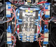
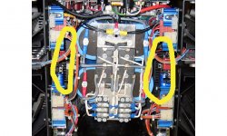
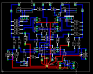
Any idea what the bigger black heatsinks, (see annotated pic below), under the driver boards are for?
Those are just ventilation louvers in the bottom sheet of the chassis. It is some what deceiving though.
Aaron,
Hang in there I'm sure you will come up with a good way to move em to safe haven....
Mark
I measured mine and don't really remember what they were running at. I suppose Iwould remember if they were unusually hot. Those two are not really afected by the bias setting either.....
I will measure and post it here tonight when I get home from work.
Mark
I will measure and post it here tonight when I get home from work.
Mark
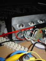
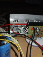
Well i did some "modding" and managed to make the drivers and bias fit between a set of emitter resistors... It was a tight fit, hard to drill and very fiddly! (Took about 4 hours for the whole move! Not sure why, or where the time went!)....
Now the drivers sit at about 35 deg (22 ambient)... So they are stone cold... heatsink (whole thing) sits at about 36 and the hottest output sits at approx 41deg (at 22 ambient)... The predrivers sit at 36deg with the alloy tabs still on them....
Bias has gone up 8mv after 30mins of running.... So it's stable... very!
I'm gonna keep and eye on it for a few hours and see how it goes... Pics follow
Attachments
Well done Aaron, that looks pretty neat. 😎
Well, as promised here is a new layout with what will be a separate driver board, not finalised yet, but you should get the idea. Tried to keep signal paths as short as possible, and avoid any inductive loops, etc.
Well, as promised here is a new layout with what will be a separate driver board, not finalised yet, but you should get the idea. Tried to keep signal paths as short as possible, and avoid any inductive loops, etc.
Attachments
Well, as promised here is a new layout with what will be a separate driver board, not finalised yet, but you should get the idea. Tried to keep signal paths as short as possible, and avoid any inductive loops, etc.
Great job on the board!! I wish it coulda been that way from day one but I guess improvements always come over time. If you do a group buy you can very definately count me in for some of those.
One thought... Would it be possible to eliminate the radial mount caps in favor of axial mount? This would keep the finished profile of the board very shallow. The only real protruding thing on it are the two 1000 mfd caps. Also turning R-126, the bias pot 90 degrees counter clockwise and placing it under R125 and to the left of Q-106 would leave that area a bit less cluttered. There is a square open area below R125 that it would neatly fit into.
Mark
- Home
- Amplifiers
- Solid State
- Krell KSA 50 PCB