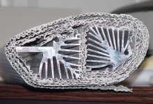
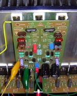
Hello, i own a KSA-150 AMP. I just wanted to offer some inside pictures in case someone is interested. I do not understand the technical stuff, but he sure sounds and looks good 😀
Acording to my manual he pushed 220wpc @ 8ohm and doubles it down to 1ohm and can drive impedances below 1ohm.
Acording to my manual he pushed 220wpc @ 8ohm and doubles it down to 1ohm and can drive impedances below 1ohm.
An externally hosted image should be here but it was not working when we last tested it.
An externally hosted image should be here but it was not working when we last tested it.
An externally hosted image should be here but it was not working when we last tested it.
An externally hosted image should be here but it was not working when we last tested it.
An externally hosted image should be here but it was not working when we last tested it.
An externally hosted image should be here but it was not working when we last tested it.
An externally hosted image should be here but it was not working when we last tested it.
An externally hosted image should be here but it was not working when we last tested it.
An externally hosted image should be here but it was not working when we last tested it.
Mark A. Gulbrandsen said:I don't think the 80 would be as difficult as you think it would be.
It certainly would if you can only make 2"x 4" PCBs! 😉
SMT Krell clone anyone?
Hi fellow builders
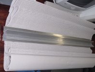
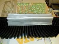
This was delivered today: my Krell "look-a-like" heatsink.
At least now I already have something to start with.
(The right-one is something to experiment with)
Still no suggestions regarding the transformer (as lgreen asked earlier).
Cheers
This was delivered today: my Krell "look-a-like" heatsink.
At least now I already have something to start with.
(The right-one is something to experiment with)
Still no suggestions regarding the transformer (as lgreen asked earlier).
Cheers
Attachments
Nice heatsink GeWa, was it expensive? The other variant looks like it would suit plastic transistors better.
As for traffos, I will be using a 30-0-30, but I believe evidence shows a 27-0-27 was probably what was used in the original.
As for traffos, I will be using a 30-0-30, but I believe evidence shows a 27-0-27 was probably what was used in the original.
They were 62,5€ inc shipping and ex VAT per metre.
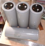
I'm also tempted to go with 30-0-30V secondaries. Gives you about 40 - 45VDC rails. Can't go to high because the cap's I ordered are rated 63VDC.
Cheers
I'm also tempted to go with 30-0-30V secondaries. Gives you about 40 - 45VDC rails. Can't go to high because the cap's I ordered are rated 63VDC.
Cheers
Nice amp Lord Maggie! Wanna send it to me for a week so I can reverse engineer it?
I accidentally had my 50 running on +-45 volts for a while. The air tunnel sinks got hotter n ell! You will need 4 outputs per rail and perhaps a but higher resistance in series with the 27 volt zeners to limit the current to them, or larger zeners. Otherwise I believe that all else will work well.... just one heck of a lotta heat to get rid of. Don't forget extra sinking for the drivers! They get hotter n ell too.
I wonder if JWB got his KMA 160 clone board up and running? In this thread.....
http://www.diyaudio.com/forums/showthread.php?threadid=42357&highlight=KMA160
Mark.
Sounds like he did from the end of the thread.
Al/ Really has to finish this Krell before starting on another...
Al/ Really has to finish this Krell before starting on another...
Hi neychi
I will let you know as soon as I have them. I ordered 4x 47000µF/63V types for my amp. It will take at least another two weeks before I can expect them.
Cheers
I will let you know as soon as I have them. I ordered 4x 47000µF/63V types for my amp. It will take at least another two weeks before I can expect them.
Cheers
A question to those who have theirs running
How much HOTTER do the drivers (main) get when going from lower bias to higher bias (like from 280mV bias to 500+mV bias)...? Should the drivers get hotter? It's about 27c ambient here at the moment (it's 7pm!) and my drivers are sitting at about 62/63deg (direct from the tab at the top of the chip)....
If i had a fan internal - is it wise to have a fan on the drivers? If it's that simple, i'm having an internal fan (for toroids, etc) but am worried that it might ruin the thermal tracking of the heatsink to the drivers - is that anything to worry about? My output sinks are all fanned - so i thought - why not drop the driver heatsink a few deg by using a fan? Is that a wise idea?
Thanks
Aaron
Actually the drivers get hotter n ell! The higher the bias goes up the hotter they get. I just don't know how the originals lasted so long myself, Krell was perhaps just on the borderline of having enough heatsinking, or the semi's can just take it. Mine ran in the mid 70's C.! Since the drivers have to support the heat sink on this version of the board and more weight on them is also not a good thing I decided to move mine to the main sink which I did sucessfully although its a bit hairy to do. I attached wires that are about 1.5" long to my devices, longer to the bias tracker, and then re-located them to the main sink right under the board where they used to be. Please note that the drivers still get that area of the sink very warm even before the heat from the output devices rises to the to that part of of the sink. Now the whole sink stays at a nice 54 deg C. Bias tracking is still excellent, perhaps better than it was. I think the reason that the original Krells did not have them on the air tunnel though was because real estate available on those smaller air tunnels was at a premium.... simply not enough room.
I would like to see this board re-designed in two ways.......
1. Eliminate the stupid currnet limiting stuff on the board....
2. Re-do the driver area on the board so the bias device and both drivers back sides are in line and facing the same way. Locate them far enough down the board so they could either be mounted to a sink similar to Krells original or to be able to mount them to the main heat heat sink by soldering them to the back of the board. Three holes would need to be provided in the board to access the screws to mount the three devices to the main sink.... this is assuming flat back sinks are being used as most have.
Mark
Actually the drivers get hotter n ell! The higher the bias goes up the hotter they get. I just don't know how the originals lasted so long myself, Krell was perhaps just on the borderline of having enough heatsinking, or the semi's can just take it. Mine ran in the mid 70's C. with 420 mv and 6 output devices! Since the drivers have to support the heat sink on this version of the board and more weight on them is also not a good thing I decided to move mine to the main sink which I did sucessfully although its a bit hairy to do. I attached wires that are about 1.5" long to my devices, longer to the bias tracker, and then re-located them to the main sink right under the board where they used to be. Please note that the drivers still get that area of the sink very warm even before the heat from the output devices rises to the to that part of of the sink. Now the whole sink stays at a nice 54 deg C. Bias tracking is still excellent, perhaps better than it was. I think the reason that the original Krells did not have them on the air tunnel though was because real estate available on those smaller air tunnels was at a premium.... simply not enough room.
I would like to see this board re-designed in three ways.......
1. Eliminate the stupid currnet limiting stuff on the board....
2. Re-do the driver area on the board so the bias device and both drivers back sides are in line and facing the same way. Locate them far enough down the board so they could either be mounted to a sink similar to Krells original or to be able to mount them to the main heat heat sink by soldering them to the back of the board. Three holes would need to be provided in the board to access the screws to mount the three devices to the main sink.... this is assuming flat back sinks are being used as most have.
3. Allow for a larger pair of driver emitter resistors
Mark
Damn 70's will be too hot!!!
I guess the only question now - can i use a fan on the board? i dont' mind doing this as it will have 12v feeds in the amp already.... But wanting to know if there is any problem with using a fan on the board?
Aaron
(edit) - I did test the fan option the other day - with a fan that was definately too powerful, but i had the drivers sitting at 30 deg - about 5 above ambient after about 20 sec!!! But the bias was RIGHT up and going up very very fast, as it is not setup for the drivers to be running at that temp!!
Aaron
I really think that is placing a band aid on the project myself. It will be just fine till the fan dies and then youe home becomes part of the movie "Back Draft". You will also have alot more noise..... Can't you move the drivers off the board? The project looks alot cleaner this way too......
Attachments
Even though mine isn't finished yet, I'm with ( the stereo version of) Mark. You've got those nice big heatsinks - use them! 😉
As regards Mark's wishes for a redesign, if people like my version, ( when it's finally finished and prototyped), then I will willingly let it be used for another GB.
As regards Mark's wishes for a redesign, if people like my version, ( when it's finally finished and prototyped), then I will willingly let it be used for another GB.
Mark A. Gulbrandsen said:I really think that is placing a band aid on the project myself. It will be just fine till the fan dies and then youe home becomes part of the movie "Back Draft". You will also have alot more noise..... Can't you move the drivers off the board? The project looks alot cleaner this way too......
Nope, putting them off the board takes up room that needs to be used to attach the heatsink to the casing... They are "big" heatsinks, but moving the drivers is messy as there will have to be wires running everywhere....
Only real solution is bigger heatsinks..... I have no other way really of doing it.... If i did find a bit of space to fit them, then wires go everywhere.... that's more what i'm worried about...... Only problem with using a bigger heatsink is the fact that i have a metal band between the 2 drivers.... So the heatsinks can only be one sided, if that makes sense....
The other option could be moving the bias transistor to the main heatsink and then using mega sinks on the drivers.... (not sure how i'd attach it!).......
Any ideas?
An externally hosted image should be here but it was not working when we last tested it.
An externally hosted image should be here but it was not working when we last tested it.
Hopefully the images gives someone some ideas to help me 🙂
Aaron
- Home
- Amplifiers
- Solid State
- Krell KSA 50 PCB