Morten,
I would use the 22k / 1.5k combo. No need to change the gain, it is optimized for the chosen design.
I think those Chinese clone boards use different parts to avoid legal problems.
I would use the 22k / 1.5k combo. No need to change the gain, it is optimized for the chosen design.
I think those Chinese clone boards use different parts to avoid legal problems.
I would also use better drivers than the suggested parts numbers for Q9 and Q10.
The VAS transistors appear to be OK, but you could also swap those out for a bigger package if dissipation is an issue.
The VAS transistors appear to be OK, but you could also swap those out for a bigger package if dissipation is an issue.
The EF VAS driver (Q105 & 106) does not need 4mA of bias current.
You could set this EF driver bias to about 1mA and the amplifier would work.
The emitter resistors R120 & R121 could be anywhere from 1k0 to 2k0, giving a range of driver bias of 0.7mA to 1.4mA
I can see that 3k3 seems very high, where the bias is only 0.4mA, but there is an advantage that Krell may have wanted. The bc550c with an hFE >400 will give a base current of <1uA.
This base current is injected into the LTP and unbalances that input LTP. This may have been a concern for Krell and the 3k3 value was the compromise they chose to minimise the unbalancing of the LTP.
Adopting 330r for R120 & R121 increases the injected current ten-fold to ~10uA
That will increase the distortion generated in the LTP.
Last edited:
Andrew,
I know 4mA is high for the EF driver. My main point in bringing up the subject was to illustrate that 400uA seemed very low for the original 2SA968 and 2SC2238 T-220 devices.
1mA would be a good setting for the EF.
In Bob's book, I recall him using 470 in his EF circuit to keep the slew rate of the EF higher than the amp itself so the EF would not limit the complete amp.
I'm going to try a 1k in the EF, compare measurements and will post.
I would also use better drivers than the suggested parts numbers for Q9 and Q10.
The VAS transistors appear to be OK, but you could also swap those out for a bigger package if dissipation is an issue.
Thanks a lot for your help!
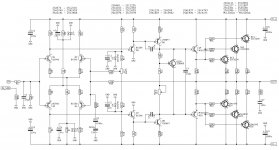
I probably need to change some transistors, yes. Would it be ok to keep the LTP as BC transistors? I have listed a few transistors above the schematic as suggestions for replacement of the components in the schematic - would these be ok? Or do you have other suggestions?
Here is schematic with a only few changes and with some transistor alternatives:
Attachments
Morten,
Any of the LTP transistors you have listed will work well. The BC transistors collector to emitter voltage is a little low. I would use your other choices listed.
Just about any transistor can be used for the emitter follower.
The VAS, driver and output transistors you have listed should work too.
The KSA50 design appears to be very forgiving and a lot of different transistors seem to work well in the circuit.
R9 and R10 set the currents through R21 & R22.
These two currents through R21 & R22 should be about equal. To achieve this you probably need to make either R9, or R10 adjustable.
The input is DC coupled.
That results in the two sides of the LTP seeing different impedances.
You output DC (offset) will jump/wander all over the place when you change, or adjust your source.
How are you planning to cope with that?
THD+N,
Nice to know transistors are good! I will change the LTP as suggested.
Did I understand correctly that the EF may be BC types?
2 less transistors needing twisted legs... ;-)
AndrewT,
I wasn't planning on coping with wandering offset issues, but now I am!
Your comment made me check the PCB, and the input capacitor is there.
I just managed not to notice one of the largest components on the PCB! Suggested value 1u .. 4u7.
About the R9 & R10: will closely matched LTP transistors avoid the problem with different currents?
And what exactly are the consequences? Offset issues?
Am I correct in assuming the current through R21 og R22 always are equal,
not considering base current to/from other transistors, since they are effectively in series?
Or is there something I overlook?
Attachments

Q9 & Q10 will not have identical base currents.
That inequality has an effect on the currents through the VAS transistors.
If the two base currents were identical then to maintain zero offset the VAS transistors must pass identical current when the output is dead centre (zero offset).
When the Q6 and Q8 currents are not equal then the offset wanders off pulling more voltage on one and reducing the voltage on the other. this offsetting effect equalises the currents.
In the real circuit we know that the two base currents are not equal so you need a method of trimming either R9, or R10 to bring the offset back to zero.
eg.
make R9 = 9k1
and make R10 = 10k
Add a parallel trimmer across R10 to give a range of adjustment of roughly 200r, i.e. from 9k0 to 9k2
The trimmer could be 91k + 20kVR
At bottom setting you have (91k+0k) || 10k = 9k01
At top setting you have (91k+20kVR) || 10k = 9k17
I would choose C1 = 4u7 MKT, or adopt the Cherry phase correction by adding 54k in series with R33 and bypassing that with an electrolytic. This allows R2 to be increased to 54k+27k = 81k
and that allows C1 to be either 1uF or 1u5F polypropylene
But I would investigate reducing R33 to somewhere around 20k, to reduce the gain from +32.2dB This is quite high.
Last edited:
AndrewT,
your comments seem appropriate, but, forgive my ignorance, isn't the offset adjusted by the trimmer RW35?
How will I know how to adjust the 20K pot and the RW35 when they both influence the offset?
your comments seem appropriate, but, forgive my ignorance, isn't the offset adjusted by the trimmer RW35?
How will I know how to adjust the 20K pot and the RW35 when they both influence the offset?
I don't see the input current injection method of compensating for input offset as doing the same job as the VAS current equalisation described earlier.
If there is some VAS inequality and one uses the Krell input current injection to compensate then you will find that the Input LTP is becoming unbalanced.
If you adopt both offset methods then you have to find a method to minimise the offsets. At the moment I can't see the wood because there are too many trees.
Maybe someone or youself can see a way to optimise the adjustment method using both to match up the LTP currents and minimise the output offset.
I don't see the input current injection method of compensating for input offset as doing the same job as the VAS current equalisation described earlier.
If there is some VAS inequality and one uses the Krell input current injection to compensate then you will find that the Input LTP is becoming unbalanced.
If you adopt both offset methods then you have to find a method to minimise the offsets. At the moment I can't see the wood because there are too many trees.
Maybe someone or youself can see a way to optimise the adjustment method using both to match up the LTP currents and minimise the output offset.
I suppose it is possible to use one of these approaches:
1 - Measure RW35 to be positioned exectly at midpoint. Then adjust R10 (R9) for zero offset. Then use RW35 for adjusting offset after warming-up, etc.
2 - Same as 1, except leave RW35 out until R10 adjustment is done. Then solder in RW35.
Would you agree?
I have not (successfully) built the Krell style offset corrector and I have not built an amplifier with both offsetters in there.
Thus I can't advise on a method. My Krell KSA100 sounded "dull" or oscillated. I couldn't find a compromise that worked and no Members advised on a solution.
I suspect that those that have an FFT analyser could find a method that minimises the highest harmonics and maybe minimise the lower harmonics as well.
Morten,
To be blunt... just build the KSA50 according to Pinkmouse's last schematic and listen to it. If you want to modify it after you get it going, then have at it.
A lot of these amps were built and they perform great. Is it a perfect circuit? No.
Use 22k/1.5k to set the gain at the right level.
Adjust the 22k offset pot to mid-resistance before you power-up the circuit, then as it warms up, you can adjust it to null any offset.
For the bias, adjust the pot for max resistance, then slowly bias the amp to the right current level based on the number of outputs and emitter resistance you used.
KSA50
AndrewT and THD+N,
Thank you for good advice.
I am going to gather the parts together. Probably most of them will be in the drawer, I hope...
I'll come back with an updated schematic and pics.
AndrewT and THD+N,
Thank you for good advice.
I am going to gather the parts together. Probably most of them will be in the drawer, I hope...
I'll come back with an updated schematic and pics.
question
sorry, I apologize x the questions, maybe I've been done here .. but it's so big .. i can not read everything x x clones ksa 100 and ksa 50 mk2 that transformers and psu serve? toroidal 600w 2x37 and capacitors from 47000uf 63v are okay? you have psu patterns, pcb , guides to point me to the pcb i've seen on jims ebay, i want them to try it .. well okay? thank you😛
sorry, I apologize x the questions, maybe I've been done here .. but it's so big .. i can not read everything x x clones ksa 100 and ksa 50 mk2 that transformers and psu serve? toroidal 600w 2x37 and capacitors from 47000uf 63v are okay? you have psu patterns, pcb , guides to point me to the pcb i've seen on jims ebay, i want them to try it .. well okay? thank you😛
I don't see the input current injection method of compensating for input offset as doing the same job as the VAS current equalisation described earlier.
If there is some VAS inequality and one uses the Krell input current injection to compensate then you will find that the Input LTP is becoming unbalanced.
Just to see if I am following here, is this design known to have offset drift when built per the Krell schematic?
I don't know, it was too long ago when I was testing it.Just to see if I am following here, is this design known to have offset drift when built per the Krell schematic?
- Home
- Amplifiers
- Solid State
- Krell KSA 50 PCB