My emitter resitor is 0r68. Heatsink 0.4C/W.
Well you recommend to lower the bias to 250mV to play safe?
Regards
Well you recommend to lower the bias to 250mV to play safe?
Regards
Hi,
your temperature does not add up.
400mV & 0r68 =145W of dissipation.
Without de-rating the two sinks, the delta T is 29Cdeg.
Add on Tc deltaT and ambient and you're probably over 60degC for Tc.
Still OK, but I suggest you fit a latching temperature switch on each sink.
What would it cost (finance & aesthetics) to double the size of the sinks?
Then you can try to fully bias the output stage to 1.9A (or a little more) instead of 1.76A
KSA 50 schematic
I like to build KSA 50. But there are many posts about this amplifier, and I confused where to start . Please help me find where is the schematic . Thank you guys.
Best regards,
Josh
I like to build KSA 50. But there are many posts about this amplifier, and I confused where to start . Please help me find where is the schematic . Thank you guys.
Best regards,
Josh
Hi blue,
you'll find all the detail here and in the links shown.
http://www.diyaudio.com/wiki/index.php?page=Building+guide
you'll find all the detail here and in the links shown.
http://www.diyaudio.com/wiki/index.php?page=Building+guide
I would be interested in a KAV-250, but it would have to be down the road once I get back on my feet. I've made progress, but not there yet.
As for me doing the kit GB, maybe in a year, certainly not right now.
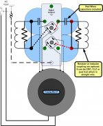
I drew this diagram of the pwr supply for the people who bought my Krell that I had to sell.
Is it worth putting in the Wiki for an example?
As for me doing the kit GB, maybe in a year, certainly not right now.
I drew this diagram of the pwr supply for the people who bought my Krell that I had to sell.
Is it worth putting in the Wiki for an example?
Attachments
Mark, any chance you can send out my Krell boards, which I paid you for almost 7 months ago, which you have not sent yet?
I had to dig this thread out of solid state - page 5!
Last night I realized that my KSA50 may be my favorite of all my amps right now. It just seems to be the one that does almost everything right - at the moment, and with the rest of my stuff.
Thanks to all that contributed.
....... now if we could only see them XA schematics🙂 😉
Last night I realized that my KSA50 may be my favorite of all my amps right now. It just seems to be the one that does almost everything right - at the moment, and with the rest of my stuff.
Thanks to all that contributed.
....... now if we could only see them XA schematics🙂 😉
troystg said:Mark "might" still have some.
Thanks. How do I ask him though? It won't let me email him.
Lee.
Are you planning on using TO3 output devices?
If yes, I still have a pair of Jan's boards sans output boards. You can have these for free if you want, just the shipping cost.
Regards
If yes, I still have a pair of Jan's boards sans output boards. You can have these for free if you want, just the shipping cost.
Regards
Thomo said:
Thanks. How do I ask him though? It won't let me email him.
Lee.
Mark G [cinerama84106@yahoo.com]
You can e-mail me at cinerama84106atyahoo.com. Just change the at to the @ and it shold go through.
I have lots of KSA50 boards available but I'll warn you that right now I am slow to ship out.
Mark
I have lots of KSA50 boards available but I'll warn you that right now I am slow to ship out.
Mark
Walter, i am very interested in your "Jan" boards if you have them still available. To pay for them is no problem to me.
I want to build one more headphone-amp with them, so i do not need the outputboards.
I want to build one more headphone-amp with them, so i do not need the outputboards.
OK Wim.
Send me a PM with your coordinates and I will mail them to you.
Because Holland isn't all that far you can have them absolutely free of charge. 😉
Regards
Send me a PM with your coordinates and I will mail them to you.
Because Holland isn't all that far you can have them absolutely free of charge. 😉
Regards

Commercial KSA50 exploration
Hi all,
I had the opportunity to investigate a commercial KSA50 Mk2, courtesy of Jozua. I didn't remove the boards, but will do so soon and reverse-engineer the circuit diagram. However, just by peeking inside revealed a few interesting facts already. There are much less difference to the Mk1 clone than between the KSA100 Mk1 and Mk2.
Similarities:
- Most of the resistor values visible are the same as the clone's, e.g. 3x 1k5 per rail, 24ohm driver emitter resistors etc.
- Same 2SC2240/2SA970 diff stage.
- Same MJE15030/15031 driver stage.
- Same 2x 1000uF feedback cap.
- Same speaker protection relay circuit as on the KSA100 Mk2.
Differences:
- No relay soft-start. If there is a thermister such as on the KSA100 Mk1, it must be tucked away very deeply as I couldn't see one anywhere.
- There is a large 2.2uF film cap on the board. It's possibly a bypass for the feedback cap.
- There are weird restors tack-soldered on top of the boards close to the input. They aren't Dales like the rest, but it also doesn't look like a DIY mod.
- As discussed sometime earlier on the thread, there are two pairs of 2SC2238/2SA968 transistors, compared to the clone's one pair. However, since there are no additional transistors, perhaps it's simply used instead of the MPSA42/92 as on the clone.
- No Mosfets or current diodes as in the KSA100 Mk2.
- The emitter resistors are 0.5ohm instead of the 1ohm used in most other commercial KSA's.
- Bus voltage is much higher than expected at 47VDC, loaded. This is with the primaries connected for 240VAC - our power is 230V so it should be around 49V. A KSA100 runs at about 56V loaded.
- Very interesting is that there is something mounted on the rear panel (looks almost like a fuse but don't didn't want to try open it since it looks kind of flimsy). It has two terminals on the inside, one connected to the right channel's positive speaker output, and the other to a certain node on the left channel's PCB. Anybody has any idea what this could be?
Pierre
Re: Commercial KSA50 exploration
Perhaps shorting the terminals will feed the rt channel OP into the left channel input diff ... thereby enabling the amp to be bridged...?
PWatts said:It has two terminals on the inside, one connected to the right channel's positive speaker output, and the other to a certain node on the left channel's PCB. Anybody has any idea what this could be?
Pierre
Perhaps shorting the terminals will feed the rt channel OP into the left channel input diff ... thereby enabling the amp to be bridged...?
- Home
- Amplifiers
- Solid State
- Krell KSA 50 PCB