kmj said:And now the vonderful voice of Mikael Kiske is flowing out of the kitchen. Next step is to connect outputdevices and repeat scope and speakers again. Then it is the other channel...
careful! And best of luck.
Hi All-
I sold my Krell KSA-50 clone kit yesterday. It was a chassis 800VA toroid, dual bridge rectifiers, four 60,000uF caps (bypassed of course), "Al PCBs and the GB component kits I made for them.
I was sad to see it go and not be able to assemble it myself.
Then it hit me...
I still have a pair of the "Jan" boards and a Pass Labs Mini-A PCB set.
The Mini-A is a 10w class A unit that can also act as a driver for a second stage bumping it up to the "A30" which was 30w.
With that in mind and knowing that the Krell "main board" can drive a small speaker driectly...
Is it possible to configure Jan's boards as a smaller 5- 10w amp using "just" the main boards? Of course the transistors would be "extended" off board via wire and mounted on suitable heat sinks.
I could justify (space, cost, need) for two 10w amps sitting in storage, but I could not justify the BIG chassis and investments in the other ones I just sold.
Any comments would be appreciated.
Hi,
have a look at the bias through the drivers.
Ib=38mA results in 23mW of ClassA output into 8ohms. The rest will be in ClassB.
The drivers are rated at 50W when cold and low Vce, expect about 10 to15W of ClassAB power if you keep them cool.
have a look at the bias through the drivers.
Ib=38mA results in 23mW of ClassA output into 8ohms. The rest will be in ClassB.
The drivers are rated at 50W when cold and low Vce, expect about 10 to15W of ClassAB power if you keep them cool.
Troy,
After building the KSA50 clone with the "jan" boards, i decided to use another set of the "jan" boards (only the driver boards, and not the power boards) to make a headphone amp.
Loek was very helpfull to assist me with all my questions to do the job, and a little playing around with the result of this "only driver board" amp, i find out that the driver wa very, very able to drive big speakers (vintage JBL XL66, 4 Ohm). It sound great and very loud!
So, to answer your question, its very good to do. You will be surprised.
Give it a try.
Indeed thats the way i tested my mainboard.
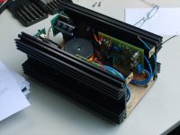
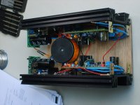
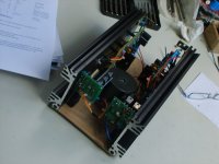
Hey Wim, maybe you can add one of the nice pictures of your mini Krell ?
Greetings, Loek
Hey Wim, maybe you can add one of the nice pictures of your mini Krell ?
Greetings, Loek
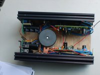
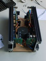
Trafo 2x25VAC 15VA, rails adjusted (regulated PSU) to +/-30VDC, 450mV over each 27 ohm resistor.
Hi Wim,
Have you tried a lower bias or a full ClassA bias compared to the 17mA you have at present?
that's very different from the 15 to 25mV that is recommended for a ClassAB bias setting.450mV over each 27 ohm resistor.
Have you tried a lower bias or a full ClassA bias compared to the 17mA you have at present?
bias
Hi Andrew, the purpose of this minikrell is a headphone amp or small poweramp just like Troy wanted.
So with 450mV the bias is only 16mA and seems a nice class A workingpoint to me.
Loek
Hi Andrew, the purpose of this minikrell is a headphone amp or small poweramp just like Troy wanted.
So with 450mV the bias is only 16mA and seems a nice class A workingpoint to me.
Loek
Hi,
I doubt that 16mA = ClassA bias.
It equates to 300mW into 600ohms.
or 150mW into 300ohms
or 15mW into 30ohms.
But, it could be a good level of high bias and stay in ClassA for much of headphone listening.
Which is what prompted the question.
Would it sound better with a bit more bias to pull up the ClassA output to cover a wider SPL range, or drop it down to optimum bias for ClassAB?
It may be best as is, but who knows?
Would it sound better with a bit more bias
Thats what i asked to Wim, maybe he will give it a try.
My amp it not operational now...
The levels you mentioned are more then your ears can have....
Thanks for the advise anyway.
Loek
Thats what i asked to Wim, maybe he will give it a try.
My amp it not operational now...
The levels you mentioned are more then your ears can have....
Thanks for the advise anyway.
Loek
This weekeind i will turn up the voltage across the 27 ohm resistor to 1 V (as i sayd earlyer, it is 450 mV now).
1V is also the voltage across the 27 Ohm resistor on my finished Krellclone with outputboard.
I will report the listening results on this forum.
1V is also the voltage across the 27 Ohm resistor on my finished Krellclone with outputboard.
I will report the listening results on this forum.
Well, who would have guessed? One channel works even if I am a bit spectic about the volume. I added an extra pair of transistors on the output and now there's three pairs of MJ15003/4 on each channel and the bias is set way down since I havn't fastened the sensor for montoring the temperature yet. With this in mind I hooked it up to my scope and got a nice, clean sinuswave as reward. But shouldn't the wave inclease in size compared to when I only used the driverboard? I haven't changed anything on the scope btw.
I did connect a tang-band 3" fullrange driver and turned the volume on the laptop up to 33% and this wasn't loud at all. When I used my old gainclone this would have scared the neighbours half to death. Oh, I used music at this point 😀
oh, could someone correct my math. To get 50W classA out of three pairs of outputdevices and a Re of 0.68ohm I should use have 400mV across the resistor, right?
sinewaves
The output stage has no voltage gain (actually a tiny loss), so the voltage you see with the driver board is all you are going to get, just with a lot more current available...
Yeah, 400mv across 0.68ohms sounds about right...~1.7A for the three pairs.
Congratulations getting it going.
Stuart
The output stage has no voltage gain (actually a tiny loss), so the voltage you see with the driver board is all you are going to get, just with a lot more current available...
Yeah, 400mv across 0.68ohms sounds about right...~1.7A for the three pairs.
Congratulations getting it going.
Stuart
- Home
- Amplifiers
- Solid State
- Krell KSA 50 PCB