Wellington must be getting pretty warm by now.
Hi Andrew,
weve had the heater going (Krell too). It has been cold but a high is coming so hopefully its going to get better. I heard also that we are in for some uncharacteristic storms this summer. Its not looking like a flash summer.
seeya arthur
lgreen said:I don't know if you know this, but when it gets THAT cold you can actually see your breath......
On a good day overhere you can't see your breath, but you can always smell it.
I miss Gengis and his hooters overhere.
Any suggestion what might be a better rectifying diode to use on the Krell instead of a regular bridge rectifier ?
MUR type, BYW99 maybe ?
For Pavel:
A little old lady answered a knock on the door one day, only to be
confronted by a well-dressed young man carrying a vacuum cleaner.
"Good morning," said the young man. "If I could take a couple of
minutes of your time, I would like to demonstrate the very latest
in high-powered vacuum cleaners."
"Go away!" said the old lady. "I haven't got any money!" and she
proceeded to close the door. Quick as a flash, the young man wedged his
foot in the door and pushed it wide open.
"Don't be too hasty!" he said. "Not until you have at least seen my
demonstration." And with that, he emptied a bucket of
horse manure onto her hallway carpet.
"If this vacuum cleaner does not remove all traces of this horse
manure from your carpet, Madam, I will personally eat the remainder."
The old lady stepped back and said, "Well I hope you've got a
damned good appetite, because they cut off my electricity this morning.
jacco vermeulen said:
***
Any suggestion what might be a better rectifying diode to use on the Krell instead of a regular bridge rectifier ?
MUR type, BYW99 maybe ?
***
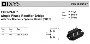
I bought a pair of IXYS VBE26-06NO7's (pdf data sheet) a year ago from somone here on diyaudio.com (at least I think they are those, but don't have them sitting here with me) and plan on using them in an upcoming Aleph X. Click here for some options of IXYS high current bridge rectifiers using ultrafast diodes (similar to MUR but 4 of them).
Don't know if they are any good but they sure look impressive, and I'm not sure how one is supposed to connect to those super sharp dangerous looking spikes on the package.
(I would have used these on the krell clone but they are larger than the standard cube full wave bridge and actually would not fit on my floorplan)
Attachments

Al,pinkmouse said:I need to get about £100 together to get the ali for my chassis, so it's waiting!
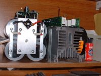
That is a very nice and compact configuration for your amp! The setup with the power supply capacitors and rectifier is very neat. Are there small LED resistors hiding in there parallel to your 5 watt resistors that I just can't see....assuming those little red dots are LEDs?
Robert
Hi Robert
Indeed there are. It just seemed like a good idea when I was prototyping, as those caps hold a huge amount of charge, and a LED across the bleed resistor gave a good indication of when it was safe to dive in with the soldering iron.
When I get the chassis together, I may split them up into pairs, two for each channel, I haven't decided yet.
I agree those LED's are a very good idea, will also help discharge the caps at a nice easy rate...
Mark
Mark
Mark A. Gulbrandsen said:I agree those LED's are a very good idea, will also help discharge the caps at a nice easy rate...
Mark
Won't the amp itself discharge the power supply at a nice easy rate, assuming everything is connected?
With or without Music playing? Also if you have a relay, then no it won't (unless the bleeders are present). If no relay with music playing, then it will bleed to some extent not all the way because once the voltage comes down to a point where the transistors are not open (biased) they will not conduct and not discharge the caps all the way.
Also I am sure someone will comment about how they need to be discharged uniformly.
Also I am sure someone will comment about how they need to be discharged uniformly.
What size resistors did you use for this? I have not used any of these before, but if they help I might want to start.
Blessings, Terry
Blessings, Terry
I have seen anything from 3.9k to 10k. Perhaps a 2watter for the lower value.
Personally I'd go higher cause the lower you go, the more "micro-ripple" you get 😉 .
Personally I'd go higher cause the lower you go, the more "micro-ripple" you get 😉 .
resistors
My front panel LEDs stay on for a few minutes after the amp is turned off. One longer than the other. I think each LED is connected to a V+ for each rail through 5K resistors. This should get you down to .7 volts at which point the diode won't conduct right? Is that enough or do you need to go to zero?
My front panel LEDs stay on for a few minutes after the amp is turned off. One longer than the other. I think each LED is connected to a V+ for each rail through 5K resistors. This should get you down to .7 volts at which point the diode won't conduct right? Is that enough or do you need to go to zero?
Question, is this led and 5k connected to only one rail on one cap?
You need to bleed all 4 caps. So if your LED is connected to +V of channel 1, you are only 1/4 of the way there. But you probably already knew that.
As far as 0.7v charge, if you have huges caps, it could cause a tiny explosion if a screw driver is dropped. Better to drain all the way for safety. However as far as forming of the cap, I don't know if it helps to have a tiny charge.
You need to bleed all 4 caps. So if your LED is connected to +V of channel 1, you are only 1/4 of the way there. But you probably already knew that.
As far as 0.7v charge, if you have huges caps, it could cause a tiny explosion if a screw driver is dropped.
Better to drain all the way for safety. However as far as forming of the cap, I don't know if it helps to have a tiny charge.K-amps said:I have seen anything from 3.9k to 10k. Perhaps a 2watter for the lower value.
Personally I'd go higher cause the lower you go, the more "micro-ripple" you get 😉 .
How much voltage is lost?
Thanks, Terry
More like 1.7 volts for a regular red LED.
The resistor drops the voltage from the rail to the LED level, like a Zener.
Suppose you have 37.5 VDC rails, regular current through a LED is 10mA ( max for a standard red LED is 20mA)
The resistor needs to drop the voltage some 36 volts.
36volts and 10mA means a 3.6K resistor.
36 volts times 10mA is 0.36 watts, a 0.6 watt resistor is enough.
A 10.000uF capacitor with 1 volt on it will have only 0.005 joule charge in it left, hardly worth the sweat.
K-amps said:...You need to bleed all 4 caps. So if your LED is connected to +V of channel 1, you are only 1/4 of the way there. But you probably already knew that.
.
Right, I am 1/2 of the way there because I have 2 LEDs on 2 rails of 4. Forgot about the Vfwd of LEDs being higher than .7, thanks for the correction Jacco, blue LED has 3.5 Vfwd. I usually calc the resistor to run them for 8-10 mA per LED. I am going to measure voltage drop on the other 2 channels and then we shall see whether the amp itself provides sufficient drain.
edit- but I agree that using those resistors is a good building practice, no reason not to do it if you can get in there and install them.
lgreen said:using those resistors is a good building practice
With LEDs it looks good, and bleeding the caps is healthy for both the capacitors and yourself.
- Home
- Amplifiers
- Solid State
- Krell KSA 50 PCB