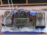
finally finished my ksa50.
Its a nice amp, good bass but not as airy and sweet top end as the aleph 2s or JLH. Mids arent as nice either I think.
Will need to have a bit more time with it to form a better opinion, but thanks to all those who helped make this project possible, and ACD for designing the boards and sorry whoever you were, I frogot, but big thanks to the first pcb group purchase organiser.
cheers Arthur
Luke
Good to hear you got the amp finished. Do you have any pictures of it? 🙂
What type/value of cap did you use for C105/C106?
Regards
Good to hear you got the amp finished. Do you have any pictures of it? 🙂
What type/value of cap did you use for C105/C106?
Regards
What is " sweet top end " ? Are we growers of cane ? Or technics ?
Hi Upupa,
its means colouration I like😀
I hope to build an amp you reccomend one day, maybe Symasym?
Ive spent a bit more time with it now, its growing on me, but youll see Im using old transformers that hum a bit. Also a bit of audible hum from speaker. Maybe a bit more work on my earthing and place the wires smarter.
Ive used 48mF 0.1 Ohm 48mF in PSU. 3 X mjl4302 and mjl1402 per channel.
GeWa,
C105, 106 are 47 pF.
here are some pics🙂
Attachments
thanks Mark, I have updated wiki.
Pinkmouse, the bias is 1.5A. Its getting hot and I think I would be pushing my luck increasing it. I think thats about 18Watts class A into 8 ohms? Can someone confirm or tell me how to calculate it?
cheers Arthur
Pinkmouse, the bias is 1.5A. Its getting hot and I think I would be pushing my luck increasing it. I think thats about 18Watts class A into 8 ohms? Can someone confirm or tell me how to calculate it?
cheers Arthur
Luke....
(Speaking in Obie Wan's voice)
You can do it.... You have to feel the bias force Luke....May the bias be with you..... Or just get some darn fans to keep her cool and go ahead and crank it up....
🙂
Mark
(Speaking in Obie Wan's voice)
You can do it.... You have to feel the bias force Luke....May the bias be with you..... Or just get some darn fans to keep her cool and go ahead and crank it up....
🙂
Mark
Luke said:the bias is 1.5A. I think thats about 18Watts class A into 8 ohms?
The KSA is a PushPull design, half of the output devices push current into the output node, the other half pulls current out of it.
The bias of 1.5 amps goes from the positive rail into the NPN device to the output, then through the PNP device to the negative rail.
With a signal on the input, the current through one output device increases, the one through the other device decreases by the same amount.
The difference goes through the output node to the loudspeaker.
With current through one device reduced to zero, current through the other will be doubled : 3 amps.
3 amps peak output current is 72 watts in 8 Ohms=> Ohms law: 3*3*8
This is 36 watts continuous class A operation in 8 Ohms.
Hi Luke,
what voltage are your DC supplies (+-Vrail) running at when the bias is set to 1.5A?
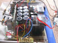
It looks like you have one heatsink (about 8inch by 4inch by 1.5inch) to each channel.
Each channel needs to get rid of heat based on Bias Current (Iq) times Total voltage supply (V+V).
e.g. 1.5 * (36+36) = 108W. For a 0.5C/W sink at 20degC ambient this is DeltaT = 54Cdeg giving a sink temp of 74degC. add on sink to case Rthcs gives a Tc about 84degC. TOO HOT.
My guess is that with a 36V supply and full Krell Klone bias of 1.9A you will need two and a half to three sinks of that size for each channel i.e. one sink per output pair.
what voltage are your DC supplies (+-Vrail) running at when the bias is set to 1.5A?
It looks like you have one heatsink (about 8inch by 4inch by 1.5inch) to each channel.
Each channel needs to get rid of heat based on Bias Current (Iq) times Total voltage supply (V+V).
e.g. 1.5 * (36+36) = 108W. For a 0.5C/W sink at 20degC ambient this is DeltaT = 54Cdeg giving a sink temp of 74degC. add on sink to case Rthcs gives a Tc about 84degC. TOO HOT.
My guess is that with a 36V supply and full Krell Klone bias of 1.9A you will need two and a half to three sinks of that size for each channel i.e. one sink per output pair.
AndrewT said:My guess is that with a 36V supply and full Krell Klone bias of 1.9A you will need two and a half to three sinks of that size for each channel i.e. one sink per output pair.
Guess again,
that is a dual flange heatsink from Conrad in Oz on the picture.
And the biggest one they carry by the looks, these do 0.25 C/W, not 0.50 !
Thanks for the lesson Jaco🙂 That makes sense. And yes your right it is the 0.25 C/W Conrad sink. Its hot but not dangerously hot.
Andrew, your right about dissipation, its 108W exactly. I think I can hold the sinks for at least 3 seconds. What I am concerned about is that one transformer is hot and the other is not. Difference is one touches the base plate, where as the other one stands off it a couple of mm. I wonder if thats what is causing one to heat and not the other. Both are well within their capacity ratings.
seeya ab
108 W of dissipation for 1 W of average output power....crazy world... 😀 And people are amazing, that glaciers are melting...
Upupa Epops said:108 W of dissipation for 1 W of average output power....crazy world... 😀 And people are amazing, that glaciers are melting...
It'd be great if that was the reason for glaciers melting - would be a lot easier to persuade folks to give up their classA amps (108W) than their cars (74000W)
It was little exaggeration, but for me is it good example, how people aren't thinking about... But it is lost fight... ML, NP, DA and others are good washers of brains... 😉
I don't think I'm brain-washed. Give me a PCB for an AB design that sounds this good and I will be happy to build it. I don't like huge heatsinks or the heat they put off. I just want to learn and have things that sound nice.
Blessings, Terry
Blessings, Terry
Terry, I have heard many amps and many from " washers " 😉 I knoe very well, what is good sound... 😉
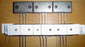
Update from the war zone
Here is a picture of my ThermAlloy trashing.
Man, you've got to admire that aluminium oxide.
You can't cut it, grind it, chop it, only break or pulverise the stuff.
Only thing that worked, or kind of, was Mark suggestion to do the Marilyn Monroe approach.
And even diamond just nibbles the crums off this material, the ThermAlloys turn red like a space shuttle re-entering.
Anyway, the way i've placed them on the Sankens means i only need to cut 1 insulator for every 3 output devices.
For the time being, with 24 MT200s, that would be only 8 of these die hard jobs.
Don't ask how many i've sent to never never land !
Attachments
- Home
- Amplifiers
- Solid State
- Krell KSA 50 PCB