still4given said:Is the LED an important part of the deal?
Does it draw down the PSU output?
Thanks, Terry
No need terry. LED just for looks (and to show how much power left) but the resistors can do the job perfectly for you. Actually NO cap set-up is complete without bleeder resistors.
lgreen said:
Right, I am 1/2 of the way there because I have 2 LEDs on 2 rails of 4. Forgot about the Vfwd of LEDs being higher than .7, thanks for the correction Jacco, blue LED has 3.5 Vfwd. I usually calc the resistor to run them for 8-10 mA per LED. I am going to measure voltage drop on the other 2 channels and then we shall see whether the amp itself provides sufficient drain.
edit- but I agree that using those resistors is a good building practice, no reason not to do it if you can get in there and install them.
Lgreen,
Sometimes an asymmetrical discharge (caused by a power LED loading only one side on the Caps) will cause the amp to oscillate while powering down.
Though not dangerous as it happens only when the caps have little charge that they cannot destroy the amp, however this can and sometimes does contribute to a "groaning" sound coming from the speaker as the caps discharge.
Therefore you need to bleed all 4 caps uniformly (and make provision for the LED on some caps vs others etc.)
pinkmouse said:I don't even need to be here, do I!
🙂
Yeah, stop complaining, it was your picture that started all this!
K-amps said:
Lgreen,
Sometimes an asymmetrical discharge (caused by a power LED loading only one side on the Caps) will cause the amp to oscillate while powering down.
Though not dangerous as it happens only when the caps have little charge that they cannot destroy the amp, however this can and sometimes does contribute to a "groaning" sound coming from the speaker as the caps discharge.
Therefore you need to bleed all 4 caps uniformly (and make provision for the LED on some caps vs others etc.)
Ohhhhhhhhhhhhhh.............. I better check that out ...... cause you cannot leave these things powered up all the time. Thanks for the tip.
Terry, the resistors (with or without LEDs) will not draw down your voltage rails, they consume less than a watt for each setup.
Well, it's funny how everything has a was of working itself out.
A guy had some trannies left over, so that problem is solved (used = Cheap, cheap is good 😱 )
One of those nice heatsinks that still4given among others use found its way to a swedish auctionsite, so the Apexjr tunnels will have to be used for something else.
Since the Sink has everything needed to mount TO-3 including isolators I can now buy mj15003/4 from the local vendour and theres no more need to buy from the states.
You just have to stop looking .
.
Since most parts is at hand and only time is lacking (oh, and GB-parts) I started to read up on the WIKI and saw something. Ok, it's kind of late to start now when I've already bought most of the stuff needed but better late than never. Anyway, I didn't notice earlier that the original KSA-50 "only" used 2 of each transistor/channel while others here uses 3xMJL21193/4 go get the same output.
So if one gets about 50W from 2pc of mj1500X..... damn, i lost track, there was something I was fishing for but thats gone

Must have been something about using different amount of transistors for the same output and same setup. Well, it will probably come back to me....
A guy had some trannies left over, so that problem is solved (used = Cheap, cheap is good 😱 )
One of those nice heatsinks that still4given among others use found its way to a swedish auctionsite, so the Apexjr tunnels will have to be used for something else.
Since the Sink has everything needed to mount TO-3 including isolators I can now buy mj15003/4 from the local vendour and theres no more need to buy from the states.
You just have to stop looking
.Since most parts is at hand and only time is lacking (oh, and GB-parts) I started to read up on the WIKI and saw something. Ok, it's kind of late to start now when I've already bought most of the stuff needed but better late than never. Anyway, I didn't notice earlier that the original KSA-50 "only" used 2 of each transistor/channel while others here uses 3xMJL21193/4 go get the same output.
So if one gets about 50W from 2pc of mj1500X..... damn, i lost track, there was something I was fishing for but thats gone
Must have been something about using different amount of transistors for the same output and same setup. Well, it will probably come back to me....
Hi Kmj,
the original used 2pairs 20A, 250W devices per channel.
The Klone output board uses 3pairs 15/16A, 200/230W devices per channel. The total current and/or power ability of the two set ups is comparable. I am using 5 or 6 pairs of 15A, 150W devices, again slightly more power but considerably more current and particularly dissipation ability(keeps Tc down).
So, in conclusion, in return for the slightly(?) reduced level of resolution you get from multiple pairs you gain in heat transfer from junction to ambient.
AndrewT
Thanks, It was probably that I was trying to grasp. I'll probably be using the 15003/4 due to it's availability and price, and I like the idé that it's the "Original" 🙂
So there isn't any need to change parts on the boards to higher powerrating then. Just go go ahead and use those supplied in the GB.
Oh, another thing. As most of you (i think) I was REALLY impressed with LGreen s creation with the fancontroll, and who wouldn't be?
So I found This , It doesn't have a warningsystem and auto-shutdown but it looks really cool
Thanks, It was probably that I was trying to grasp. I'll probably be using the 15003/4 due to it's availability and price, and I like the idé that it's the "Original" 🙂
The total current and/or power ability of the two set ups is comparable
So there isn't any need to change parts on the boards to higher powerrating then. Just go go ahead and use those supplied in the GB.
Oh, another thing. As most of you (i think) I was REALLY impressed with LGreen s creation with the fancontroll, and who wouldn't be?
So I found This , It doesn't have a warningsystem and auto-shutdown but it looks really cool
Parts
Troy,
I assume you would be reluctant to organize another group buy after your heroic efforts on the last one.....and no one would blame you.
My question relates to the parts BOMs.....have they been corrected, as far as you know, to reflect the fitting topology of the boards? I happen to have the Pinkmouse boards and am anxious to order some parts.
Thank you for all your efforts!!!!!
Robert
Well I think this parts GB is difficult because it IS 2 different boards and some parts are different.
The Loooooong delay was Welborne. This shorter one is mine. I have new Excel spread sheets made for both Al and Jan's BOMs.
I have started filling in the ACTUAL part #'s I ordered and that work.
I have test fitted those parts and was waiting to get paid again(today) before I ordered the replacement parts for the ones that don't fit or are incorrect. My wife turns her head to me spending some of my paycheck, but will not allow me to take from the savings for this hobby. Says we need to keep it for the kids college, weddings and bail... 🙂
The kits were seperated and in bags when I started the random sample test. I have kept the bags and and the addressed boxes, it is just a matter of finishing up the correct part per board procurement.
Mouser is VERY fast in delivering to me so I am doing all the ordering I can through them.
attached is a copy of the excel SS. I am still updating it. As you can see I have not finished test fitting the transistors.
Attachments
rabstg said:attached is a copy of the excel SS. I am still updating it. As you can see I have not finished test fitting the transistors.
So do the white cells in the Done column mean they don't fit, or just that you haven't had a chance to try them out?
kmj said:So I found This , It doesn't have a warningsystem and auto-shutdown but it looks really cool
Hmm, that link is for what looks like a dodgy set of computer speakers.
kmj said:AndrewT
So I found This , It doesn't have a warningsystem and auto-shutdown but it looks really cool
With 8 OP devices on 37v rails, why is Lgreen "afraid" of testing 1 ohm loads, You have an Arc Welder there my friend!

Speakers??? Arcwelder???
We are talking about a Fancontroller, atleast that is whay pops up on my screen.
We are talking about a Fancontroller, atleast that is whay pops up on my screen.
Comments based on the link you sent. ( I quoted the wrong one in the reply) I meant the Lgreen build and Test webpage. Lgreen makes the comment of not testing his baby below 3 ohms for "safety" reasons. I am just saying that his output stage should be able to drive 1 ohm loads no problem!
He has 8 OP devices that can pump 8A each before hitting the SOAR. NPN=32A and PNP=32A.
I am assuming a 30v rail (full power into 0.5 ohm) so if the amp pushes 30v per rail, He can easily drive 1 ohm loads (even lower) assuming the heatsink is relatively cool.
He has 8 OP devices that can pump 8A each before hitting the SOAR. NPN=32A and PNP=32A.
I am assuming a 30v rail (full power into 0.5 ohm) so if the amp pushes 30v per rail, He can easily drive 1 ohm loads (even lower) assuming the heatsink is relatively cool.
Hey, that's my amp! Yep, my arc welder sure sounds great, and looks great too, well i'm still getting used to the look and feel that I need some more yellow paint in there... maybe on the fan supports... and then theres that LED issue... Whatever, still working even after all my poking and prodding. Have not even hurt myself. Lets recap, 4 pairs of 250W, 15A TO-3 devices per channel, 64,000 uF per rail, runnng at +60C on an average day here in SD.
Thought everone agreed that without protection circuitry it was not very safe to test into <2 ohms?? Should I go for it?
KMJ- that will probably work, but keep looking, you may want to use the latest and greatest
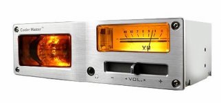
EDIT-- the following is a sound controller so it won't work for controllng the fans, but its cool anyway becuase of the vacuum tube. (see attached), Musketeer 3. People actually buy this to ADD distortion. Go figure.
Also, the prices on these computer items depreciate rapidly, and supply runs short. Mine is 1/2 the price it used to be. It lacked a disk/software so I was sure it could work stand-alone, just needed a +12 and +5 volt power supply.
I say try it out, other than adding a ton of noise to your system it should be great (just kidding- run it off a separate supply/transformer and should be fine).
Thought everone agreed that without protection circuitry it was not very safe to test into <2 ohms?? Should I go for it?
kmj said:
KMJ- that will probably work, but keep looking, you may want to use the latest and greatest
EDIT-- the following is a sound controller so it won't work for controllng the fans, but its cool anyway becuase of the vacuum tube. (see attached), Musketeer 3. People actually buy this to ADD distortion. Go figure.
Also, the prices on these computer items depreciate rapidly, and supply runs short. Mine is 1/2 the price it used to be. It lacked a disk/software so I was sure it could work stand-alone, just needed a +12 and +5 volt power supply.
I say try it out, other than adding a ton of noise to your system it should be great (just kidding- run it off a separate supply/transformer and should be fine).
Attachments
KMJ- that will probably work, but keep looking, you may want to use the latest and greatest
Oh, I'm not looking for the newest and most advanced stuff, I just like those gauges
ok
Yeah, they have a nice retro look to them. A lot of these controllers are not symetrical...did I spell that right? That one is and should be perfect.
Yeah, they have a nice retro look to them. A lot of these controllers are not symetrical...did I spell that right? That one is and should be perfect.
Matching the small trannies
I'm in the process of matching the Mpsa42/92,s for HFE only since that's all I can measure at present.
The batch of mpsa92's go from 131-200 hfe
The batch of mpsa42's go from 64-85 hfe . I have 5- 42's that are in the same range as the 92's, but not enough without buying more.
How critical is this circuit and where in the stages would you put the higher hfe's?
I'm thinking small at the input and higher near the end stages?
Good or bad thinking?
David
AVWERK said:How critical is this circuit and where in the stages would you put the higher hfe's?
Not at all critical. Just pick the closest matching ones.
- Home
- Amplifiers
- Solid State
- Krell KSA 50 PCB