Good news!
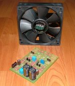
I stopped at the hobby store on the way home from work and bought on of these.
I checked the temp of the output devices at 300mV with the small fan and got 40c. So I cranked up the bias to 400mv across the 0R68 resistors and I'sitting right at 52c on the devices themselves. I guess I must have tender fingers cause I sure thought they were hotter than that. I'm going to let it run for another hour or so and check again but I'm pretty happy right now.
Blessings, Terry
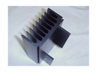
Apexjr is selling heatsink tunnel w/fan for $25 per pair.
http://www.apexjr.com/images/APEXJRTUNNELHEATSINK2.jpg
http://www.apexjr.com/images/APEXJRTUNNELHEATSINK2.jpg
Mark A. Gulbrandsen said:Where did you get those from? Is that an off the shelf sink?
Mark
They are a standard Avid Thermalloy extrusion. I bought a dozen of them off of eBay. They are 10" in length and in pairs form a 4.75" square air box. I machined off the tabs to maximise the area to mount flatback devices.
Regards
Anthony
still4given said:I guess I must have tender fingers
Ask Mrs Terry !
Maybe some may be interested in how your Krell compares to Elliot's 101 now.
Good chance your devices will be below 80C with the sink running at 52C, 80C die temperature is was i copied from a lot of class A designs.
(you're not the only one feeling relieved, i think i posted your heatsink was capable of running 2 channels with a fan on top when you showed us the critter)
Terry,
Let the Krell run for three or four hours before you make any serious comparisons!! It makes a big difference over say just an hour or so.......
Mark
Let the Krell run for three or four hours before you make any serious comparisons!! It makes a big difference over say just an hour or so.......
Mark
if i am allowed to add to this :
i like to have front ends on separate rails.
Keeping the front end running all the time costs very little, and imo extends its life, at the expense of a few low tag capacitors.
To my experience class A amplifiers took/take at least an hour to reach their peak performance.
By keeping the front end hot all the time the output stage reaches 90% of its potential within 15 minutes.
With the kind of bias i love that saves money and time, only adds one switch.
You just love to make people envious of your resources, Anthony.
still4given said:Good news!
I stopped at the hobby store on the way home from work and bought on of these.
I checked the temp of the output devices at 300mV with the small fan and got 40c. So I cranked up the bias to 400mv across the 0R68 resistors and I'sitting right at 52c on the devices themselves. I guess I must have tender fingers cause I sure thought they were hotter than that. I'm going to let it run for another hour or so and check again but I'm pretty happy right now.
Blessings, Terry
Terry 400.0mV puts you right at 50 watts class-A. One word of caution with those IR thermometers, keep the horizontal. If you make readings holing it vertical pointing down at the heatsink, the warm air rising from the heatsink heats up the polycarbonate covering of the IR sensor thereby giving you a false reading. The device is calibrated to measure with the plastic cover not being subject to non-ambient temperatures..... at least thats how mine acts.
Cheers!
K-
jacco vermeulen said:
Ask Mrs Terry !
Maybe some may be interested in how your Krell compares to Elliot's 101 now.
Good chance your devices will be below 80C with the sink running at 52C, 80C die temperature is was i copied from a lot of class A designs.
(you're not the only one feeling relieved, i think i posted your heatsink was capable of running 2 channels with a fan on top when you showed us the critter)
Hi jacco,
Actually that 52c is the reading I get pointing the meter directly at the transistor cases. The heatsink is only reasding between 35c and 40c. Maybe I should get another one tho check it against. It reads 33.2c when I point it at my skin.
I will run some more tests against the P101 when I can.
Blessings, Terry
cooling
Terry, I'm glad you realized that its not as hot as you thought!
One easy thing you can do that I have not seen mentioned here is to add a second fan so you have one at the inlet and one at the outlet. I'm in the process of doing that myself. You can improve airflow and turn down the speeds to make them less noisy. If you are tight on space there are narrow (10-15 mm thick) fans out there that should fit.
Mr Green,
performance of a fan differs for sucking or blowing.
With one fan blowing, the other sucking the air, one of the two fans will be working much harder, and will wear down a lot faster.
You may experience a substantial noise level increase with that setup, far more than the 3 dB for using two fans.
Stacking them is more common, i posted a link to an article a number of weeks ago:
www.electronics-cooling.com/Resources/EC_Articles/MAY96/may96_01.htm
Too Late?
Only recently found this thread - can't believe my luck, it's immense.
Have been frantically trying to catch up, got up to page 231, had assumed that I had missed out on this second group buy, but just jumped to the end and looks like it is boarder line.
I would like to build three pairs monoblocks, so would love to come in on the latest purchase if its not too late?
I looked at the link to the Wiki but it says it's closed? Could just be me as I don't have much experience of using these types of things.
So if it's not too late please count me in for 6 sets of boards (or enough for 3 pairs of monoblocks) including the PSU boards if poss.
Go back one page, locate a post by Mark A. Gulbrandsen and send him an e-mail. He is the one coordinating the group purchase efforts.
Hi Bud,
I think Mark announced that he was delaying finalising numbers from Sunday to Thursday (tomorrow).
Get your payment instructions & PayPal Mark double quick, he is a few hours behind us.
I think Mark announced that he was delaying finalising numbers from Sunday to Thursday (tomorrow).
Get your payment instructions & PayPal Mark double quick, he is a few hours behind us.
jacco vermeulen said:Mr Green,
performance of a fan differs for sucking or blowing.
With one fan blowing, the other sucking the air, one of the two fans will be working much harder, and will wear down a lot faster.
You may experience a substantial noise level increase with that setup, far more than the 3 dB for using two fans.
Stacking them is more common, i posted a link to an article a number of weeks ago:
www.electronics-cooling.com/Resources/EC_Articles/MAY96/may96_01.htm
Interesting, I was wondering about this. I've got the ability to control each fan's speed independently so maybe I can get them even. Plus, if each one is only working at 75% of its operating voltage, even if one works harder than the other, say up to 85%, it won't wear out faster because its still operating less than spec anyway.
Parts kit GB
Hi All-
Mark is busy with the board GB so I won't bother him with getting a kit together from the surplus shop.
If anyone feels frisky and can come up with the BOM and part #'s I will order, kit and send out the parts at cost.
And since the second rev board has the same components as the first, the kits should work on both.
I am thinking we need the following:
1. Dale resistors minimum
2. All small components be included
3. Optional TO-247 devices to fit in the OP boards
4. Simple instruction manual for building and testing

- Home
- Amplifiers
- Solid State
- Krell KSA 50 PCB