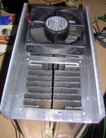
The complete module from the bottom showing both fans. Each heatsink is held in place to the c-channel with 4 long threaded rods. The two bottom edges of the c-channel will be drilled and tapped with 3 - 8/32 threads on each side for mounting to the chassis bottom. Air intake will be through the bottom of the chassis.
Attachments
Hi Mark,
I have just compared your voltage measurements to the schematic Delta Audio 13-2-2005.
The DC balance around the LTP seems odd.
The common voltages between one stage and the next are often different. e.g. q109E 0.728v should equal Q1B 0.969v
Can you re-confirm as you suggested?
What value of Re are you using? Is Rb1 = shorting link?
Can you measure the voltages across the LTP emitter resistors R114, 115, 118, 119? This measurement may be difficult, try twisting the MM leads together and ensure they do not pass near your high current cables, transformer etc. To check for balance in the LTPs and to see how the two complementary halves compare.
You may be right or it may be a typo. I plan on re-measuring with a different meter later tonight. My RE=.68 ohms and yes, no RB, just a shorting link. All my part values are identical to what was used in the KSA-50 MK2 except the output devices which are 3 each MJL21193/94. I did notice some slight drift in one of the regulated supplies as well. It only has a max 1A output.
Mark
P.S., I did go back and look at my list and the Q-109 Emitter was a typo error, Both it and the OP base should read .725V. while Q-110 E should be .733 and the base of the OP devices the same. So it was just a typo. Once this is for sure I would appreciate it if someone could add it to the building WIKI, I won't have time before I leave for my service trip tommrrow to post it. Any time I spend on this project on the road for the next week or so will be e-mailing everyone with totals due and such for the board WIKI.
Thanks!
KMJ.... aah.. the price...??
Well... heatsinks ARE expensive I'm afraid...🙁
But- since you are in Gothenburg.... you should have a good junk yard within your reach... Old mainframe hard disk units used to have tunnel heatsinks...
Also- why don't you check the Fischer web site to find the appropriate sink and give Walstrøm AB a call...
In another thread last year, another swedish co. was mentioned...Webra ---- www.webra.se... I think.............. search the forum....
Hi mark,
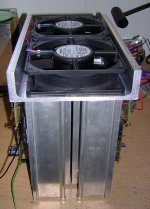
What are those thick white isolators under the drivers?
Do you have the same isolators under the output devices?
I assume they have good electrical insulation values.
Do they also have good heat conductivity values?
Can I suggest that the Vbe multiplier should be closer to the output devices or does it not matter here due to the very long time constant of the heatsink?
What are the two white cables feeding ( the back widget at the end of the heatsink)?
A nice looking setup - well planned and executed.
Updated Voltage Measurement List
OK, Using two(different) regulated variable supploes here is what I measured in refrence to ground.......
Note: Bias is set to 150 mv across the emitter resistors and 8.9 mv offset... after 1/2 hour warmup. Rb is jumpered, RE=.68 ohms.
Q-101
E .745
B 142.9 mv
C +36.07
Q-102
E .442
B 143 mv
C - 35.6
Q-103
E .617
B 0
C +35.9
Q-104
E .320
B 0
C -35.75
Q-105
E +36.5
B 35.95
C 0
Q-106
E -36.32
B -35.7
C 0
Q-107
E +37.05
B +36.5
C +1.29
Q-108
E -36.8
B -36.33
C -1.288
Q-109
E +.728
B +1.296
C +38
Q-110
E -.733
B -1.296
C -37.88
Q-111
E -1.06
B -.563
C +1.296
+ side OP device
E 120 mv
B +.728
C +38.09
- Side OP Device
E 140 mv
B -.733
C -37.89
Later tonight I will compare it with the other channel as I think a couple measurements may be off or perhaps I didn't have the probe in good enough contact. Ya got to be careful !
Mark
AuroraB
Wow, thanks 🙂
I'll check out the companys but I cant salvage from junkyards, it's not allowed here 🙁
Wow, thanks 🙂
I'll check out the companys but I cant salvage from junkyards, it's not allowed here 🙁
What are those thick white isolators under the drivers?
Those are Thermaloy alumnium oxide/ceramic insulators. These effectively replace the berylium oxide type insulators. They are expensive but very efficient. Luckily I can get them surplus.
Do you have the same isolators under the output devices?
Yes, They are exactly the same thickness, .80", so thermal time constant should be about equal. Thermal tracking and settle down time is excelent. I feel the bias device is in just about the right place for this heatsink. My forst version had the drivers and boas at the top of the sink and actually that works out very well as the bias device tracks the driver temperature and then the entire sink equalizes with in about 15 min. anyway. But the second version seeme to equalize faster. Note that the bias device is just under an inch from each of those center output devices.
What are the two white cables feeding ( the back widget at the end of the heatsink)?
Which picture and which widget? There are three white wires. The two outers are the drive to the output boards and the center wire is the feedback from the output.
Mark
Mark A. Gulbrandsen said:The complete module from the bottom showing both fans. Each heatsink is held in place to the c-channel with 4 long threaded rods. The two bottom edges of the c-channel will be drilled and tapped with 3 - 8/32 threads on each side for mounting to the chassis bottom. Air intake will be through the bottom of the chassis.
are those heatsinks as large as I think they are

post 3055:It shows the upper leg resistor of the multiplier with a value of ???.
Its on the wikipage under item R124: 4700 ohm.
Loek
Its on the wikipage under item R124: 4700 ohm.
Loek
Mark,
Thanks you so much for taking the time to do the chart. I know this is going to help me to find my problem. I won't be able to check today because of the Holiday but will do it tomorrow for sure.
Hi Andrew,
I will go through the steps you suggested as well. I didn't use the low bias pot or resistor. I wasn't sure how to hook it up and someone said it wasn't necessary. Maybe I left too much stuff off of this board. I wish it hadn't had all of the unnecessary things on it. It made it confusing for me.
Oh, and I used 4.7K
apassgear,
No I didn't check it before. I am getting dead on readings from each sides and both ends. I'm sure I have the cap oriented correctly. I did check each of them for polarity before soldering them into place.
I will run you little test just to be sure.
Thanks again everyone.
Blessings, Terry
Actually not really very large at all...... The flat back is 10" X 7", the large fins are 2", the shorter fins about half that. They were reallycheap off of E-Bay, something like 10 or 15 bucks each. Having built other amps over the years I did'nt bother to calculate the thermal specs, I can keep it at 50 deg. C. in a 70 deg. F. ambient room with the fans running at about half speed. They are actually Solid State Motor Deive heat sinks.
Everyone..... disregard that first voltage list! Use the second one. Terry, Are both light bulbs the same?????
Andrew, Here is a Link to those thermalloy Aluminum Oxide Ceramic insulators.
Mark
Everyone..... disregard that first voltage list! Use the second one. Terry, Are both light bulbs the same?????
Andrew, Here is a Link to those thermalloy Aluminum Oxide Ceramic insulators.
Mark
Mark A. Gulbrandsen said:Updated Voltage Measurement List
Q-101
E .745
B 142.9 mv
C +36.07
Q-102
E .442
B 143 mv
C - 35.6
Mark
Great help as always Mark!
Can you please put these voltages on the KSA-50 build Wiki as reference.
Also to calculate the paypal payments, how much is it per main board/ outputs/other boards or whatever we decided,
cheers!
K-amps
Everyone..... disregard that first voltage list
Time is going fast and hoped to have some measurements but i dont see it is happening this month...
Loek
Time is going fast and hoped to have some measurements but i dont see it is happening this month...
Loek
Mark A. Gulbrandsen said:Actually not really very large at all...... The flat back is 10" X 7", the large fins are 2", the shorter fins about half that. They were reallycheap off of E-Bay, something like 10 or 15 bucks each. Having built other amps over the years I did'nt bother to calculate the thermal specs, I can keep it at 50 deg. C. in a 70 deg. F. ambient room with the fans running at about half speed. They are actually Solid State Motor Deive heat sinks.
Everyone..... disregard that first voltage list! Use the second one. Terry, Are both light bulbs the same?????
Andrew, Here is a Link to those thermalloy Aluminum Oxide Ceramic insulators.
Mark
Are you going to have any extras of these sets of PCBs?
for some reason I added my name in June but it wasn't there when I checked today 🙁 🙄
Maybe I did it and don't remember .... 🙁
Noobe,
Go ahead and add your name is it was there before, just add it at the bottom.
Will post this as soon as I hear back from Advanced, probably tommrrow. I just want to be sure there are no additions in cost for the hole size changes before I post the final price.
Mark
Go ahead and add your name is it was there before, just add it at the bottom.
Also to calculate the paypal payments, how much is it per main board/ outputs/other boards or whatever we decided,
Will post this as soon as I hear back from Advanced, probably tommrrow. I just want to be sure there are no additions in cost for the hole size changes before I post the final price.
Mark
still4given said:No I didn't check it before. I am getting dead on readings from each sides and both ends. I'm sure I have the cap oriented correctly. I did check each of them for polarity before soldering them into place.
I will run you little test just to be sure.
I was not reffering to the polarity of the caps but the polarity of both the seconary windigs on the trafo.
The trafo should have a schematic some place on a sticker and show the 4 leads - two from each secondary- is common practice to show a dot to each starting coil lead or show the color of the starting lead.
Make sure you have the ending lead of one secondary and the starting lead of the other coil to the common of the power supply.
This will be the correct center tap to be connected to the common of the PSU.
Re: MJ21193/4
Not for just the MJ21193/4, the driver included.
All bjt's stay below a volt for Vbe for low currents
I took three drops instead of two, because of the cascoded mje15032, silly really.
For the bias to the driver its in the order of 2 diode drops plus voltagedrop over the Re.
Posting measured stuff is better, so no more techno from me.
The Al2O3 insulator discs can be had from Burklin in Germany, i have a company account there. Prices of TO3's Al2O3 insulators start at 85 pence, TO247's at 70 pence.
thermal resistance for TO3 insulators in Al2O3 = 0.3 C/W. in Mica its 0.4 C/W.
Al2O3 insulators for TO3 have a 2.9 mm thickness, for TO247 and others they're 1.5 mm thick and have an even more attractive C/W rating compared to Mica.
I got Magura some of their TO3 discs, according to him its very difficult to obtain these insulators overhere nowadays.
AndrewT said:re post 3026 - MJ21193/4, Vbe(on)=2.2v.
Not for just the MJ21193/4, the driver included.
All bjt's stay below a volt for Vbe for low currents
I took three drops instead of two, because of the cascoded mje15032, silly really.
For the bias to the driver its in the order of 2 diode drops plus voltagedrop over the Re.
Posting measured stuff is better, so no more techno from me.
The Al2O3 insulator discs can be had from Burklin in Germany, i have a company account there. Prices of TO3's Al2O3 insulators start at 85 pence, TO247's at 70 pence.
thermal resistance for TO3 insulators in Al2O3 = 0.3 C/W. in Mica its 0.4 C/W.
Al2O3 insulators for TO3 have a 2.9 mm thickness, for TO247 and others they're 1.5 mm thick and have an even more attractive C/W rating compared to Mica.
I got Magura some of their TO3 discs, according to him its very difficult to obtain these insulators overhere nowadays.
Everyone..... disregard that first voltage list! Use the second one. Terry, Are both light bulbs the same?????
Mark [/B]
I'm only using one light bulb. The light bulb is plugged into the variac and then the transformer is plugged into the lightbulb circuit.
apassgear said:
I was not reffering to the polarity of the caps but the polarity of both the seconary windigs on the trafo.
The trafo should have a schematic some place on a sticker and show the 4 leads - two from each secondary- is common practice to show a dot to each starting coil lead or show the color of the starting lead.
Make sure you have the ending lead of one secondary and the starting lead of the other coil to the common of the power supply.
This will be the correct center tap to be connected to the common of the PSU.
Yes, I have the trafo schematic. I hooked the primary wires in paralled and the secondary in series. I get approx 30VAC from center tap to each lead and aprox 60VAC from lead to lead.
Blessings, Terry
- Home
- Amplifiers
- Solid State
- Krell KSA 50 PCB