agree with you,but I don't have any figures;AndrewT said:Hi Zen,
I have not tried to measure the effect but output noise will change as the NFB values are scaled up or down.
Do you have any figures?
I will -in Mark's boots-just change few bits'n'pieces and listen what I have with this......
maybe,one day-too short in time right now.....but....when I lay my dirty hands on any iteration of KSA pcbs........

Zen Mod,
Mark is on work assignment in Wyoming, and will be back next week.
So, this is why he was working so hard to get it up and running this past week.
Zen, thanks again for the trannie help, but I tried to email you from your earlier reply and it was bounced back, so I went through the forum mail, and then Mark said you tried me, and got the same problem. It sounds like EdcorUSA trannies will let me ship back that underpowered transformer, and will consider building one that meets the requirements of running those OD3 gas tubes...
However, I guess I didn't get that info fast enough to them, and because I teach elementary kids, 8 year olds, I did not get a single break till this afternoon to call Edcor, and by then, the shop was closed.
I'll just have to put off any building this weekend, suffer with my modified Grounded Grid, wimpy? Krell Klone 50, and ProAc 2.5 clones
(somebody in Australia said boomy bass?-they must have built it wrong--great bass). Perfect bicycle weather in Utah...leaf colors way up...and I have some fresh music to spin...😎
LuckyLyndy said:Zen Mod,
Mark is on work assignment in Wyoming, and will be back next week.
So, this is why he was working so hard to get it up and running this past week.
Zen, thanks again for the trannie help, but I tried to email you from your earlier reply and it was bounced back, so I went through the forum mail, and then Mark said you tried me, and got the same problem. It sounds like EdcorUSA trannies will let me ship back that underpowered transformer, and will consider building one that meets the requirements of running those OD3 gas tubes...
However, I guess I didn't get that info fast enough to them, and because I teach elementary kids, 8 year olds, I did not get a single break till this afternoon to call Edcor, and by then, the shop was closed.
I'll just have to put off any building this weekend, suffer with my modified Grounded Grid, wimpy? Krell Klone 50, and ProAc 2.5 clones
(somebody in Australia said boomy bass?-they must have built it wrong--great bass). Perfect bicycle weather in Utah...leaf colors way up...and I have some fresh music to spin...😎
if blablabla@neobee.net isn't functional to you,you can always use mail via board(btw-you didn't enable this function to ya) or you can use sasica5ATgmail.com........
bicycle weather......one day I'll put few pages on my little web with my bicycles.........and one day I hope that I'll have more time to spend on them...
btw-this days I'm looking american chopper series season one in late night hours......pretty amusing stuff 😉
nice off topic in pretty pale thread

Mark,
This transformer was exactly the one that was fitted in the mk-II model. Krell used a smaller one in their mk-I model. Its obvious that the mk-I transformer was a little bit to weak for the purpose.
Regarding physical format: Krell used a very special core in this transformer and I think it was capable to feed the amp with at least 1-1,2kW of continuos power if needed (this will give you ca 2.4kWatts in a stereo unit which is the upper limit for my house main fuses rated at 10Amps/2.3kW). Also it had a lot of windings including an electro static shield and the whole thing was then potted in a steel can.
Also I must add this: the only chance we had to recognize that this model was used in the KSA 100mk-II was by the model number for the mk-I given her by PWatts (thanks Pierre for that) and for the research they did at Avel Lindberg.
Avel do not have Krell-models connected to unique numbers, they only have model numbers to reference. To find the transformer used in the KMA-100 Avel need to have the transformer model number at first.
And finally, whats your price limit for a transformer for this amp, I think $ 543 (exclusive freight and customs) for a stereo unit will be in the upper most level for most of us if choosing the originals.
PWatts:
I could hardly wait for the pics.
Regards 😎
That seems like a pretty small toroid to me for this amp... I was thinking more in the area of 1.5KVA per channel... Its hard to believe that it was only 800 to 900 VA as they were quite large toroids. As for the front end supply we don't know yet what the specs and type of supply it was...
Flodstroem, perhaps you should ask Avel about the KMA-100 toroid instead. Then all secondary windings necessary will be present. As long as there is 115+115 I'm fine and you guys can fight it out ver other odd voltages you may need. Otherwise I'll skip this GB sonce its smaller than I wanted.
This transformer was exactly the one that was fitted in the mk-II model. Krell used a smaller one in their mk-I model. Its obvious that the mk-I transformer was a little bit to weak for the purpose.
Regarding physical format: Krell used a very special core in this transformer and I think it was capable to feed the amp with at least 1-1,2kW of continuos power if needed (this will give you ca 2.4kWatts in a stereo unit which is the upper limit for my house main fuses rated at 10Amps/2.3kW). Also it had a lot of windings including an electro static shield and the whole thing was then potted in a steel can.
Also I must add this: the only chance we had to recognize that this model was used in the KSA 100mk-II was by the model number for the mk-I given her by PWatts (thanks Pierre for that) and for the research they did at Avel Lindberg.
Avel do not have Krell-models connected to unique numbers, they only have model numbers to reference. To find the transformer used in the KMA-100 Avel need to have the transformer model number at first.
And finally, whats your price limit for a transformer for this amp, I think $ 543 (exclusive freight and customs) for a stereo unit will be in the upper most level for most of us if choosing the originals.
PWatts:
On a side note, I've just completed Jozua's rebuilt MK2 amp. Will post pictures tomorrow of the measurements made with a) his commercial Mk1, b) his commercial stock MK2, c) the rebuilt Mk2, d) the KSA50 clone I built for him. The frequency spectra are very interesting!
I could hardly wait for the pics.
Regards 😎
HI
I just follow these project until today . But now I decided to go on and build one KSA -100 to even I'm a owner the KSA-50 clone .
I went to the Wiki page were is the list for the interest on the PC board to ad my name but some how I'm unable to put my name into the list properly .
It always comes at the last row outside , not between the lines .
I would like to ask for help if someone can fix that to me .
My user name
gaborbela - Canada and I'm up for 2pc board
Thanks
Regards
I just follow these project until today . But now I decided to go on and build one KSA -100 to even I'm a owner the KSA-50 clone .
I went to the Wiki page were is the list for the interest on the PC board to ad my name but some how I'm unable to put my name into the list properly .
It always comes at the last row outside , not between the lines .
I would like to ask for help if someone can fix that to me .
My user name
gaborbela - Canada and I'm up for 2pc board
I signed the wiki before. Now I cant find my name. Who trashed the wiki ?
rolandong,
I also signed on the wiki earlier in this thread and suddenly I was deleted. It was because the whole side was changed to a new side I think. All of us had to sign once again, so must you.
Need help, give me a tip.
Regards 😎
I also signed on the wiki earlier in this thread and suddenly I was deleted. It was because the whole side was changed to a new side I think. All of us had to sign once again, so must you.
Need help, give me a tip.
Regards 😎
Thefirst wiki was only there to determine how much interest there was. The new wiki is permanent and you will need to sign back up. if you can't edit the wiki please make a post here as to how many boards you need and I will collect those names and edit them into myself. We should be able to nail down the exact pcb price as soon as I am back in town middle of next week.
Mark
Mark
wiki & ksa100 boards
I don't quite get the wiki and I don't want to muck it up. Could someone tack me on for 2 boards? I'm not lazy just a little numb these days.
Cheers,
Shawn.
I don't quite get the wiki and I don't want to muck it up. Could someone tack me on for 2 boards? I'm not lazy just a little numb these days.
Cheers,
Shawn.
 Jah,
Jah,PWatts said:Z2003: Even though we know it, it was also neat to observe how the spectra changes as the amp warms up. Even after 10minutes under load, the THD is still higher than it should, with the harmonics sticking up high. After about 30mins everything has settled, and yields the optimal results.. always nice to verify stuff we think we hear 😀
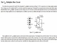
This KSA100 klone may be a good design to experiment with using On-Semi's ThermalTrak MJL3281A / MJL1302A output transistors with integrated on-die thermal diodes, plus the Leach Vbe multiplier circuit. Having the thermal compensation diodes on the output silicon could improve the warm-up characteristics.
Is anyone planning on using On-Semi ThermalTrak MJL3281A / MJL1302A on their KSA 100?
Attachments
OK here's a sobering thought: apparently the "upgrade" I made from the commercial Mk2 was a step backwards, so much so that the owner now prefers both his Mk1 and KSA50 clone above it  Before the upgrade the Mk2 was hands-down the winner. Apparently now the bass is untight and doesn't extend as low as either of these. Can anyone offer insightful (non-black magic) advice as to what could be the reason? None of them out of a purely engineering standpoint should have any adverse effect, and many of them were used in either the KSA50 clone or upgrades to the Mk1. This may perhaps not be directly related to the KSA100 clone project, but may be insightful when it comes to component selection.
Here're the changes I made between the two listening sessions.. I list every single one even though many are negligible:
- Changed the transformer primaries from 110V to 220V since it was imported from the USA. The previous listening test used a 3kVA stepdown transformer.
- Changed the feedback capacitor to a 1000uF Black Gate. The original used 500uF, but going up on the capacitance isn't a problem. I used the same cap on both the KSA50 clone and when I upgraded the Mk1 last year, with improved results
- Changed the MJE15030/31 drivers and vBE multiplier to 32/33's since I didn't have any of the others and it proved successful in the KSA50 project and Mark also used it in his prototype
- Changed the output transistors to MJ21194/21193. This is the only major upgrade IMO but it cannot make such a large difference. I used the same ones on the KSA50 clone
- Reduced the bias from 110W to 80W to make it run cooler in the hot South African climate. I did the same on the Mk1 without any adverse effect since the speakers are an easy 6ohm load, and the KSA50 clone is of course even lower.
- Added a 2uF MKP cap on the mains voltage at the transformer primaries at the wire harness in the front
- Added 100nF caps across the AC at the rectifiers (I did that with the Mk1 too)
- Changed the hookup wire with very expensive silver-coated OFC from van den Hul (on owner's request)
- Changed the input coax to van den Hul (ditto) - the same coax is used on the outside going to the preamp, and was also used in the KSA50 clone.
- Replaced the old trimpots. These, the driver transistors and the BG cap were the only changes I made to the PCB itself.
- Changed the fuse to a 6.3A one.
I forgot the flashdisk with the measurements at work where I took them, but they don't reveal anything much.. I never measured it before I changed the primary voltage, dropped the bias and changed the cap though, only after that. The other set of measurements were taken after the other changes listed here. Frequency response is, just like the other two amps, basically flat down to DC.
So.. any ideas? Since I don't have the amp with me anymore and it's far too heave to lug around, the first steps will be basic. First off the amp will just be "played in" for a while, since the BG caps apparently takes a long time until it reaches proper performance but I don't believe any of it. Then take out the cap on the mains (since I know some people experienced it to be a step backwards in some instances; perhaps the 2uF is a bit high too), and then up the bias back to 100W. If desperate the 100nF's too. If that doesn't help, it's a massive operation to revert back to the MJE15030'31's and MJ15003/15004's.
Before the upgrade the Mk2 was hands-down the winner. Apparently now the bass is untight and doesn't extend as low as either of these. Can anyone offer insightful (non-black magic) advice as to what could be the reason? None of them out of a purely engineering standpoint should have any adverse effect, and many of them were used in either the KSA50 clone or upgrades to the Mk1. This may perhaps not be directly related to the KSA100 clone project, but may be insightful when it comes to component selection.Here're the changes I made between the two listening sessions.. I list every single one even though many are negligible:
- Changed the transformer primaries from 110V to 220V since it was imported from the USA. The previous listening test used a 3kVA stepdown transformer.
- Changed the feedback capacitor to a 1000uF Black Gate. The original used 500uF, but going up on the capacitance isn't a problem. I used the same cap on both the KSA50 clone and when I upgraded the Mk1 last year, with improved results
- Changed the MJE15030/31 drivers and vBE multiplier to 32/33's since I didn't have any of the others and it proved successful in the KSA50 project and Mark also used it in his prototype
- Changed the output transistors to MJ21194/21193. This is the only major upgrade IMO but it cannot make such a large difference. I used the same ones on the KSA50 clone
- Reduced the bias from 110W to 80W to make it run cooler in the hot South African climate. I did the same on the Mk1 without any adverse effect since the speakers are an easy 6ohm load, and the KSA50 clone is of course even lower.
- Added a 2uF MKP cap on the mains voltage at the transformer primaries at the wire harness in the front
- Added 100nF caps across the AC at the rectifiers (I did that with the Mk1 too)
- Changed the hookup wire with very expensive silver-coated OFC from van den Hul (on owner's request)
- Changed the input coax to van den Hul (ditto) - the same coax is used on the outside going to the preamp, and was also used in the KSA50 clone.
- Replaced the old trimpots. These, the driver transistors and the BG cap were the only changes I made to the PCB itself.
- Changed the fuse to a 6.3A one.
I forgot the flashdisk with the measurements at work where I took them, but they don't reveal anything much.. I never measured it before I changed the primary voltage, dropped the bias and changed the cap though, only after that. The other set of measurements were taken after the other changes listed here. Frequency response is, just like the other two amps, basically flat down to DC.
So.. any ideas? Since I don't have the amp with me anymore and it's far too heave to lug around, the first steps will be basic. First off the amp will just be "played in" for a while, since the BG caps apparently takes a long time until it reaches proper performance but I don't believe any of it. Then take out the cap on the mains (since I know some people experienced it to be a step backwards in some instances; perhaps the 2uF is a bit high too), and then up the bias back to 100W. If desperate the 100nF's too. If that doesn't help, it's a massive operation to revert back to the MJE15030'31's and MJ15003/15004's.
Hi all,
We really need to get a handle on this or there may be others very dissapointed with the outcome or not know any better for lack of comparson.
I posed these questions earlier and no-one came forward with suggestions.
Please, have a long hard think and let's try and get this right first time!
here's a sobering thought: apparently the "upgrade" I made from the commercial Mk2 was a step backwards
We really need to get a handle on this or there may be others very dissapointed with the outcome or not know any better for lack of comparson.
I posed these questions earlier and no-one came forward with suggestions.
Please, have a long hard think and let's try and get this right first time!
Originally posted (331) by AndrewT
there seems to be a dual identity regarding KSA50 Klone bass developing.
Some are saying that the 50 has really strong deep bass and others are consistently saying the 100 beats it every time.
Is the power supply the difference between the two opposing sides, or is it in the implementation/selection of the PCB components?
Whichever, we need to understand the mechanism to ensure that all the builders of the 100 get the full benefit of this renowned bass ability.
Originally posted (361) by AndrewT
Hi,
jacco said quote:
"A bunch of folks here built a bunch of different KSA50s (Klones), judging one variant doesn't speak for another. "
That was the point of my earlier question.
Which components control the bass quality in the final build of a KSA50 Klone? That knowledge can and should be used to ensure the 100Klone build gives the result that most would expect.
We could start by comparing the differences between the common parts of the two 100s and how they are different from the 50.
The LTP seems similar,
The VAS seems similar,
The FET stage (mk2) is different,
The driver stage is doubled,
the driver bias is reduced,
the output stage is doubled and the bias is +40% (reduced per transistor),
the transformer is bigger,
the capacitance is bigger?,
the layout is different,
What else can be added to the list?
What components in the difference list can be eliminated from the bass investigation? Any?
What components are left that may have an effect on the bass quality?
Excellent comments. From what has happenned in this case, it would seem apparent that various tweaks that may offer improved performance in some cases may not necessarily hold true.
Based on these observations I think the window for investigation can be made smaller than the ones jacco mentioned earlier, since many stayed the same during the conversion process such as power supply, layout, front-end, number of driver/output transistors, output bias. They may of course have an influence, but in this case they all stayed the same, yet the bass had changed. Since the change is so profound, these may be the starting point for many seeking the difference between the 50 and the 100 too. Differences with transistor proximity may also influence the mixed comments even with the same transistors used.
First off I'd suggest somebody do a side-by-side comparison of the different driver and output transistors. Everybody says "I'm using xxx and it sounds so much better than yyy", but did anybody ever make an observation of comparing some directly in the same amp? Another possibility that obviously only holds true in certain instances might be that the higher fT (4MHz instead if 2) of the 21193/94's may not be as happy as the 15003/4's with the fairly long leads going to the transistor bases on the original heatsink: almost 20cm for the rear ones.
Same goes for the driver transistors.. I can't see why but maybe the higher-gain models don't work too well with the drivers and/or vBE multiplier.
PSU and capacitance would IMO be secondary, since the Mk1's bass is apparently not as good as the Mk2's, yet they use the same power supply - only difference is the capacitors and transformers are newer models, but the same values and VA ratings.
I know many of these should make no difference in a theoretical sense, but since there was a change, and a big one at that, it would appear that further investigation may be warranted. Unless somebody finds out what's going on, people wishing to play it safe may want to stick as closely to the original as possible.
PWatts said:OK here's a sobering thought.............................
Black Gates;
they realy need long burn in......I mean longgggggggggggggggg.
some ppl use AC jig for that,for sorta pre-burning.
you can try temp substitute with any decen cap,I can bet that's culprit
Well on the Mk1 that very same BG model in the same application offered an improvement straight out the package.. 😕
before you try to analyse too soon.
if you used new BG's.
they don't sound that good new, they have to broken in.
and they do take a while.
obersvations from many posts in these forums from BG devotes.
allan
edited too late already stated by others
if you used new BG's.
they don't sound that good new, they have to broken in.
and they do take a while.
obersvations from many posts in these forums from BG devotes.
allan
edited too late already stated by others
Well no.. with crocodile leads I guess I can tap the 825ohm's one lead and ground and thus have a parallel connection but that'd probably do more harm than good. Too little space to get in there with a soldering iron due to all the heatsinks, and only the front is accessible. Removing the boards is a massive task since 8 wires for each channel have to be soldered loose, and then on again, and possibly once more to remove it again later.
All in all much easier to just give the amp high-amplitude input without a speaker connected to give the BG lots of cardio workout 😉
All in all much easier to just give the amp high-amplitude input without a speaker connected to give the BG lots of cardio workout 😉
- Home
- Amplifiers
- Solid State
- Krell KSA 100mkII Clone