Regarding noisy fans:
still4given:
A tip,
Have you seen this:
http://www.coolermaster-usa.com/Products.aspx?pid=889
13dB-A not any bad value. Very cheap to.
Maybe this fan is to small, I dont know because I always use convection cooling.
Regards 😎
still4given:
You are right, I did complain about the fan noise.
A tip,
Have you seen this:
http://www.coolermaster-usa.com/Products.aspx?pid=889
13dB-A not any bad value. Very cheap to.
Maybe this fan is to small, I dont know because I always use convection cooling.
Regards 😎
Just a little over 1.5 feet per second, you'll need at least 4 to 5 times as much to avoid a big heatsink.
The 50.000 hrs is likely taken at 20C/~70F, don't expect heaven at 50C/~120F for such a fan type.
For the price you can toss one after a couple of years.
The 50.000 hrs is likely taken at 20C/~70F, don't expect heaven at 50C/~120F for such a fan type.
For the price you can toss one after a couple of years.
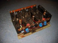
Heat sinks
I put the calipers on them and each one measures verbatim to the attached Wakefield. I don' tknow how to calculate what it can cool, nor do I know how to estimate such things on an amps output devices. I was wondering if you guys could give me some approximations? I aquired the amazing KSA-50 boards recently, perhaps a fit or even the 100? I guess it is pending bias current and number of output devices.
I'm looking for ball park #'s if possible.
Cheers,
Shawn.
Attachments
whoops...sorry
missed the number and length part...
you have a total of about 0.1c/w, so you can dissipate the output from a ksa100 with little or no fannage...cool, literally and figuratively
Stuart
missed the number and length part...
you have a total of about 0.1c/w, so you can dissipate the output from a ksa100 with little or no fannage...cool, literally and figuratively
Stuart
no fannage
Thanks!
Good for two channels or one? I don't want fannage! 😉
Shawn.
Stuart Easson said:you have a total of about 0.1c/w, so you can dissipate the output from a ksa100 with little or no fannage...cool, literally and figuratively
Stuart
Thanks!
Good for two channels or one? I don't want fannage! 😉
Shawn.
well...
...as in all things there are way too many variables to make really definitive statements...
But if you build the amp with 44v (loaded, ~48v unloaded) rails (minimum for 100w/8ohms), and run the bias at 2.5A (~100w class A/8ohms) you have 2x44x2.5 watts per channel, or 440w total. With your sinks and close to perfect distribution of heat and airflow you would get a 44c rise above ambient, normally assumed to be 20c, for a total heatsink temp of 64c, ~160f. Your sinks would be a little too hot to touch, but nothing would explode...personally I'd start at 1.5A bias and slowly run them up to the point where the heat was about 'right', ie no burning of people/cats etc, but enough so the amp is 'slamming' properly.
So both channels, no fans needed there, but not a whole lot of extra headroom either...
As I said before, good find...
Stuart
Zen Mod said:
even if I saw more than few amps with 150-180 K in feedback leg (and I mean on bip based diff stage ,not jfet or mosfet) ......mebbe is 100K and 4K1 and 10UF more appropriate........in that case- 3db corner will be under 4Hz
I'm sure that difference will be audible.
who knows?
mebbe even without 10UF,just dc coupled,with one eye on the scope 😉
just an example
Attachments

Member
Joined 2002
still4given said:
Blessings, Terry
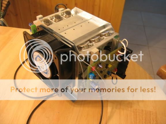
this thing is going to get hot ?
All those devices running in Class a mode. I bet that fan has to be running and pushing/pulling air at all times right ?
J'
film caps in NFB loop
Hi Zen,
when you read the article that goes with the JLH80W, you see that he chose the parallel pair of 4u7F plastic caps first and then calculated the resistive components to suit.
The problem is that he chose too high a turn over frequency resulting in -1db @ 27Hz. The lower leg resistor value should be raised by a factor of 3 to 10 times. Then the gain is way below JLH's target, but much closer to the gain many others use today.
But the really attractive use for this technique (and still keep the low value NFB resistors) would be dedicated use for mid driver or treble driver when the high pass turnover point can be tolerated at 100Hz or even much higher.
Avel Lindberg Krell Clone Transformer
Hi.
Have received an answer from Avel L. regarding ordering the original KRELL 100mk-II transformer.
This is not a cheap consumer transformer, it is a high rated super-fidelity transformer and it will be produced with specs., exactly the same as the originals once upon a time was.
Primaries will be changed to 115V+115V (for the todays mains voltage in Europe and USA)
Ratings: 800-900VA (including a very special core) + shield + steel can + colored flexible leads.
Price quote I received was as follows:
1-4pcs: £ 160 (ca $ 305)
5-29pcs: £ 145 (ca $ 271.50)
Avel ship worldwide.
Though I am in the need of 4 pcs we already have entered the lower price brake here if someone else want to order one or two transformers.
Guess it will be hard to reach the next price brake which will occur if a GB order more than 29pcs.
Should we start a Wiki for a KSA 100mk-II Clone transformer GB?
Regards 😎
Hi Flod,
if any/many UK buyers join the GB, is there any chance of tappings to suit 240Vac available in the UK?
120,115,0,115,120Vac tappings.
What about two 10 to 15Vac windings @ 200mA for those that want regulators on the front end?
Although I will not be joining the GB, I vote for opening a Wiki to gauge interest.
I think separate secondaries for KMA-style regulators are an excellent idea.. that way it can be incorporated at minimum space and cost premium.
I've emailed the final Gerbers to Mark yesterday so he should be able to proceed with the PCB GB the moment he's back home.
I've emailed the final Gerbers to Mark yesterday so he should be able to proceed with the PCB GB the moment he's back home.
AndrewT,
I shall specify all winding data in the forum later to see what is usable for todays builders. I think some of the original windings could be skipped or changed to other values as the good example you suggested in your recent post here.
Just now I could only suggest a main voltage winding that is 0-115, 0-115-125
The two 10-15V (or what ever voltage suggested) winding for a regulated power supply for front end/ pre voltage drivers would be an easy thing to incorporate.
I would like to have your comments about the primaries, is original specs alright or should we make some changes?
Regards 😎
Hi,
or
Does it not matter since both will be in series when connected to 240Vac?
would that unbalance the VA rating of the two primaries?main voltage winding that is 0-115, 0-115-125
or
Does it not matter since both will be in series when connected to 240Vac?
AndrewT, In series yes:
If connecting to 230 or 240V (0-115 + 0-115 or 0-115 + 0-125)
If connecting to 115 V: 0-115 paralleling with 0-115 (125 not connected).
Regards 😎
If connecting to 230 or 240V (0-115 + 0-115 or 0-115 + 0-125)
If connecting to 115 V: 0-115 paralleling with 0-115 (125 not connected).
Regards 😎
That seems like a pretty small toroid to me for this amp... I was thinking more in the area of 1.5KVA per channel... Its hard to believe that it was only 800 to 900 VA as they were quite large toroids. As for the front end supply we don't know yet what the specs and type of supply it was...
Flodstroem, perhaps you should ask Avel about the KMA-100 toroid instead. Then all secondary windings necessary will be present. As long as there is 115+115 I'm fine and you guys can fight it out ver other odd voltages you may need. Otherwise I'll skip this GB sonce its smaller than I wanted.
Mark
Flodstroem, perhaps you should ask Avel about the KMA-100 toroid instead. Then all secondary windings necessary will be present. As long as there is 115+115 I'm fine and you guys can fight it out ver other odd voltages you may need. Otherwise I'll skip this GB sonce its smaller than I wanted.
Mark
- Home
- Amplifiers
- Solid State
- Krell KSA 100mkII Clone