Hi Kofi,
I've just started building my own Uniamp.
Done differents choices for the parts and transformers (James OPT that I really appreciate) but your BOM is really close to mine!
This topic (from the next door forum) may help you for choke,ground,phase splitter connection, etc...
DIY Audio Projects Forum • Millett UniAmp Build Thread
This answer from Pete Millet about grounding is interesting:
Quote:
It's rather hard to see, but the "RECT CT" pin on the PCB is wired to the center tap of the HV winding on the power transformer. There is also a wire from the CT (at the transformer) to a ground lug that is located right next to the white power resistor (I think the black wire). This lug is the chassis ground point. Wires (green) also run from there to the (-) side of the output jacks (and also, on this particular power transformer, a shield/ground pin).
The resistors were an afterthought. The B+ was too high using the transformers I had, so one of the resistors (the white one) is in series with the choke, and the brown one is connected from B+ to GND (big bleeder resistor). This is just to drop the B+. You'll also note I removed the first filter cap so the way I built it it's actually a choke-input filter.
Pete.
I hope this could be helpful 🙂
And sorry for my english (I'm french and quit school long time ago 😡)
Cheers
Pascal.
Thanks for the reply, paskwalito!
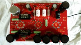
I'm looking through that thread now. I think I see what Pete is getting at here. I just finished stuffing the first board today (see photo) and I ran a ground wire from the first supply cap off the board.
I'm looking through that thread now. I think I see what Pete is getting at here. I just finished stuffing the first board today (see photo) and I ran a ground wire from the first supply cap off the board.
Attachments
Last edited:
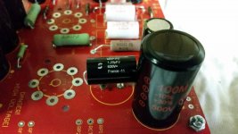
Don't know if you can see it, but here's the ground wire I rigged up. I tried to make it look inconspicuous but, well. ...
Kofi
Kofi
Attachments
Last edited:
Hi Kofi.
If you use a choke input filter (like Hammond 193J or 193H) the first supply cap (C11) is not necessary (never mind what PSUD II simulate).
R6 must be jumpered (as you done) but R7 must be open (short only for unbalanced input).
For your ground wire (the black wire you've soldered under the board to the C11 negative pin) I think it's OK and you can attach it to your chassis.
But an e-mail to Pete about C11,R6,R7 and grounding could be safer (if we are lucky and if he's not too busy he will answer quickly!)
Cheers.
Pascal
If you use a choke input filter (like Hammond 193J or 193H) the first supply cap (C11) is not necessary (never mind what PSUD II simulate).
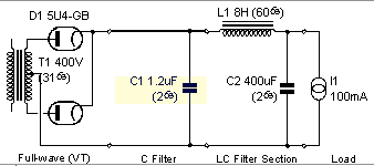
I'm not using a choke input-- see the attached image. This is my PSU.
R6 must be jumpered (as you done) but R7 must be open (short only for unbalanced input).
Oh! I totally misread that! I thought it would need to be shorted for unbalanced.
Thank you so much for catching this!
For your ground wire (the black wire you've soldered under the board to the C11 negative pin) I think it's OK and you can attach it to your chassis.
That's good news.
But an e-mail to Pete about C11,R6,R7 and grounding could be safer (if we are lucky and if he's not too busy he will answer quickly!)
Uh oh. You mean there's something not safe about this? Can you elaborate?
Ugh.
Kofi
Attachments
Oh, wait. I think you mean that it would be better to contact Pete for guidance, not that there's anything unsafe.
Man. I can misread just about anything....
Kofi
Man. I can misread just about anything....
Kofi
Kofi you don't use the choke (your Edcor's listed in you BOM) 😱
If you use it and if you don't put C11 it's a choke input filter (an LC filter instead of a CLC).
Better contact Pete to be sure of what to do!
Pascal
If you use it and if you don't put C11 it's a choke input filter (an LC filter instead of a CLC).
Better contact Pete to be sure of what to do!
Pascal
I think there's some confusion here. I am indeed using a CLC filter in the PSU. The first filter cap will be 1.2uF which, although lower than the value on Pete's schematic, is necessary for me to arrive at the proper supply voltage.
The 8H choke comes after the 1.2uF cap. The 400uF (100uF x 4) cap completes the PSU.
Does that make sense?
Kofi
The 8H choke comes after the 1.2uF cap. The 400uF (100uF x 4) cap completes the PSU.
Does that make sense?
Kofi
Kofi there's no confusion!
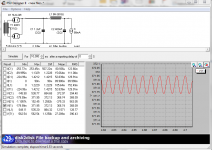
I have seen your first simulation on the first page of this thread and understood that you put C11 (1.2uF instead of 47uF) to reach 370V on B+.
But don't forget that's only simulation and that PSUD2 is not perfect with constant current source.
Pete told several times and in his schematic that C11 must not be installed with choke (LC filter,only choke and 400uF caps!).
Tomorrow I will send an e-mail to Pete just to be shure for R6,R7,C11 and grounding.
Cheers.
Pascal.
I think he means that you would not use C11 if you intend to use a choke input supply (an LC), which is correct. I intend to use a capacitor input (a CLC), so C11 is required.
Thanks for your reply. Please let me know how Pete responds.
Kofi
Thanks for your reply. Please let me know how Pete responds.
Kofi
Kofi,
Pete has responded this evening (he's a nice guy) to my 3 questions:
1.For RCA input (using the Sowter 3575 without Negative FeedBack)the good place to solder it on the board is INP and ING1 (with R6 jumpered and R7 open)?
2.Is it possible to adjust B+ by decreasing the value of the first cap of CLC
filter(C11)?
With a choke of 10H/65 Ohms,when I simulate it on Duncan's PSUD2,to reach 370 Volts on B+,C11 must be around 1,5uF (instead of 47uF).
3.Is it necessary to ground the board to the chassis?
If so,what's the best place?
the answer is clear:
So easy 🙂
Pascal
Pete has responded this evening (he's a nice guy) to my 3 questions:
1.For RCA input (using the Sowter 3575 without Negative FeedBack)the good place to solder it on the board is INP and ING1 (with R6 jumpered and R7 open)?
2.Is it possible to adjust B+ by decreasing the value of the first cap of CLC
filter(C11)?
With a choke of 10H/65 Ohms,when I simulate it on Duncan's PSUD2,to reach 370 Volts on B+,C11 must be around 1,5uF (instead of 47uF).
3.Is it necessary to ground the board to the chassis?
If so,what's the best place?
the answer is clear:
1. Yes, that would be the correct connection.
2. Yes, you can vary the first capacitor to change the voltage. The current ripple in the choke goes up (it gets closer to a choke input filter), but I think with 1.5uF you should still be OK. If the choke makes a buzzing sound, that would be why. You can also let the B+ voltage be higher... 400V is fine as well, if you use 450V caps.
3. Its always a good idea to connect the chassis to the mains ground, for safety. Its also a good idea to connect the circuit ground to the chassis, at one point. It probably will not matter a lot where you connect it - you could use the ING2 pin, for example. If you have hum or noise problems you can try moving the ground connection elsewhere, like to the negative end of the second filter cap of the power supply (C12, etc.)
Pete
So easy 🙂
Pascal
Good stuff. Thanks, pasqwalito.
I don't have any other updates yet, but I'm going to get in some work tomorrow. If everything works out, I'll be lighting the first channel tomorrow.
Kofi
I don't have any other updates yet, but I'm going to get in some work tomorrow. If everything works out, I'll be lighting the first channel tomorrow.
Kofi
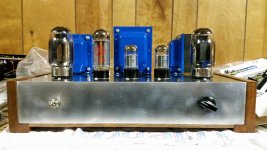
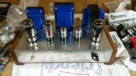
Wow. So, I had a few issues today with getting the board in the chassis. I didn't take into account the height of the electrolytics and it initially looked like I was going to wish I was dead.
Luckily, i was able to perform a few Cirque du Soleil moves and got it in perfect. Then I realized I wouldn't be able to solder the transformer leads with the board installed.
Super great day.
Anyway, I got all the rubber grommets on the chassis and installed the transformers and front panel done. Pretty nice.
Kofi
Attachments
Last edited:

Great job Kofi.
Instead of soldering transformer leads on the board I use PCB screw terminal connectors (it's cheap and so useful).
And this way no Houdini contortion!
Pascal
Instead of soldering transformer leads on the board I use PCB screw terminal connectors (it's cheap and so useful).
And this way no Houdini contortion!
Pascal
Instead of soldering transformer leads on the board I use PCB screw terminal connectors (it's cheap and so useful).
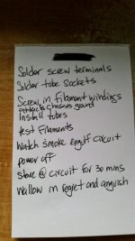
Good advice! So, I got some PCB screw terminals and they will be perfect.
I should be able to light the first channel today. I've attached my checklist for review.
Kofi
Attachments
- Status
- Not open for further replies.
- Home
- Amplifiers
- Tubes / Valves
- Kofi's Uniamp