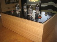
Honestly, it ain't that nice. It's pretty utilitarian, in fact. Red oak and aluminum spray painted with black appliance epoxy paint, which hides all mistakes. Tung oil on the wood.
Easy peasy.
Kofi
Easy peasy.
Kofi
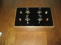
Simple does not mean it ain't nice. Me I like it. Still 8n2 I use for that c1/c9 Riaa capacitor btw.
Still 8n2 I use for that c1/c9 Riaa capacitor btw.
Good to note. I have a cavalcade of different caps so I can mix and match.
So, I started wiring the regulated filament supply yesterday and it's possible I'll finish it today. I'm rectifying the AC and then splitting it out to two different regulators, which I hope will be OK. Comments here would be appreciated.
Also, it may be time to discuss overall grounding. Obviously, this is critical in phono stages, so any recommendations would be great. I have had great success with grounding the Thorsten El-Cheapo and was intending to use the grounding scheme for that design, but if anyone has any other advice...
Kofi
Bcs grounding is a practical matter, follow your proven practice, and see if its silent again. In case of problem, we will start the usual scenario throwing trial and error odyssey, don't worry!😀
For heaters, just do what Bench indicates on his schematic so to start on something tested. Is it what you do?
For heaters, just do what Bench indicates on his schematic so to start on something tested. Is it what you do?
Kofi Annan said:So, I started wiring the regulated filament supply yesterday and it's possible I'll finish it today. I'm rectifying the AC and then splitting it out to two different regulators, which I hope will be OK.
Do you mean two different regulators for different voltages, or different channels? I don't see a problem with either, but I don't think it's necessary. You can run everything 6V and both channels with one reg..
Sheldon
You can run everything 6V and both channels with one reg..
Hmm... this is really preferable as I'll be chaining the off-board PSU to the audio circuit using a four-pole Speak-On connector. This means I'd ideally be sending the HT+, HT-, f+ and f- to the "clean" box, which further means that one 6.3V supply would be the way to go for me.
What's the best way to wire the heaters for all four tubes in this configuration?
Kofi
Kofi Annan said:What's the best way to wire the heaters for all four tubes in this configuration?
Look closely at Steve's schematic. The wiring diagram and pin assignments for the heaters wired for 6.3V are on the schematic. It might be easier to follow if you redraw it, but it is correct as shown. Basically, all four tubes are wired in parallel. For the 6DJ8, between pin 4 and 5. For the AY7, one side is to pin 9, the other side to pins 4,5 (which are connected together). Only thing I would add is to float the heaters at around 50V.
Sheldon
I saw the heater wiring in Steve's schematic, but he's got two supplies whereas I was thinking I could get away with only one. Is there something I'm missing?
Me at least I prefer 2 regulators, one for a couple of such tubes, because in the long run I have seen LM317s with good enough heat sinks failing due to hot environment when used for 4 such tubes @ 6.3V.
salas said:Me at least I prefer 2 regulators, one for a couple of such tubes, because in the long run I have seen LM317s with good enough heat sinks failing due to hot environment when used for 4 such tubes @ 6.3V.
I run 6 tubes on mine, but it's sinked directly to the chassis top plate.
Sheldon
Strange HASH-ing noise from this phono preamp
Sorry to interrupt the discussion at this stage but the Steve Bench version of this preamp with Salas's riaa C1 capacitor change and Sheldon's LED for the cathode (bypassed) resistor. Today, I finally got rid of a slight hum but I'm getting an audible haaasssshhh-ing noise which seems to me like valve noise.
-- I'm using EH 12AY7 and Valvo E88CCs, all shielded by metal caps.
-- PS is VR'ed via a TL783 directly fed from a CLC filter.
-- Heaters: Bridge rectified 6.3V taps on PS transformer into 2 x 10Kuf, bypassed by smaller electrolytic and film caps down to 0.01uF.
-- Input valve cathode bypassed resistor (2K8) replaced by a green LED on each channel as per Sheldon's - without the B+ connection.
-- Also tried red leds as well as the bypassed 2K8 resistor. Made no difference.
When I still had the hummm problem I used to get a similar noise and I changed to the new valves. This seemed to have solved the problem, but today as I fiddled with the power supply to solve the hum problem and reduced C1 (from 11n to 8n) I got this noise again, now more audible because there is no humm.
Can someone point me to possible causes of this strange noise.
Thanks in advance for your help.
Joe A
The 8n2 I like, but absolutely Riaa correct is with 6n8.
We have done the LED too and it does not add hiss even when not running with proper current extra drawn fro B+. We just did not like it that much. Best way is to take working box in hand and move it around. If the noises change, its a field.
We have done the LED too and it does not add hiss even when not running with proper current extra drawn fro B+. We just did not like it that much. Best way is to take working box in hand and move it around. If the noises change, its a field.
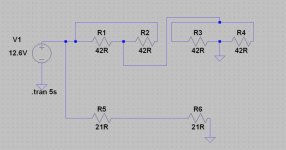
OK-- so I have been reviewing the filament wiring issue and since Jack wound me a transformer with only 1A of current availability I think I have to go with the series / parallel configuration to reduce the overall current draw on the transformer.
With the attached configuration, I believe the total current draw for the filament windings will be about 600mA, which is below the current peak for my iron.
Take a look at my guess at the filament winding configuration and please let me know if you agree.
Kofi
With the attached configuration, I believe the total current draw for the filament windings will be about 600mA, which is below the current peak for my iron.
Take a look at my guess at the filament winding configuration and please let me know if you agree.
Kofi
Attachments
Sheldon said:
OK, here are the data for one channel, without and with MC step up. Input to reverse RIAA was adjusted to give an output voltage of 1.00 at 1kHz. The largest deviations for the MM were -0.19dB at 6kHz, and +.26dB at 20K. The MC was +0.4dB at 20K. Not shown; maximum difference between channels with MC step up, was 0.16dB at 20k. Between 20 and 14kHz is 0.1dB.
Hz MM MC
20 1.01 996mV
40 1.01 1.00
60 1.01 1.01
100 1.01 1.01
200 1.01 1.01
400 1.01 1.01
600 1.00 1.01
1k 1.00 1.00
1.5k 995 996
2k 990 991
3k 982 984
4k 979 981
6k 978 981
8k 985 985
10k 984 990
14k 996 1.01
16k 1.00 1.02
18k 1.01 1.03
20k 1.03 1.05
Sheldon
Intrigued as I was by your results, just because my sand state phono stages had no problems driven by the attenuator I had, I scratched my head and thought that maybe the step up and valves were stressing. So I devised a new one. 1/200 division, copper shielded, attenuates gen noise and keeps gen at healthy output when I need 0.5mV signal. This time with much lower shunt resistor. At last the step ups proved to feel at home now, and the measurements picked up in the bass to normal. Thanks Sheldon.
salas said:I did run one sim and it looks doable.
I just confirmed real-world do-ability from the regulated PSU side. The filament supply is working. I ran it across a 21R resistor and I was able to get 12.6 steady DC volts.
Phase I Status: --COMPLETE--
--Kofi--
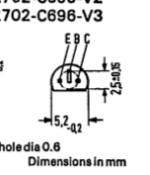
So, I'm starting the layout for the HT regulator and I'm confused about the pinout for the BC560B. I have reviewed the datasheet, but I'm confused about whether the pinout view is from the top of the device looking down or from the pins looking up.
I've been burned by this before, so take a look at the attached section of the datasheet and set me straight, please.
Thanks,
Kofi
I've been burned by this before, so take a look at the attached section of the datasheet and set me straight, please.
Thanks,
Kofi
Attachments
- Status
- Not open for further replies.
- Home
- Amplifiers
- Tubes / Valves
- Kofi Annan in: "Cascodin' with Steve Bench's RIAA!"