You have one ECC88 and one 12AY7 per channel. Those tubes have 2 sections, hence 4 triodes on each channel schematic. ECC88 is only 6.3V anyway. Pin 9 is screen.
So what I suggested was to configure each 12AY7 for 6.3V and make a 317 300mA CCS to feed them in series. Then make a 365mA 317 CCS to feed the two ECC88 in series.
12AY7 300mA @ 6.3V both sections. Common heater.
ECC88 365mA @ 6.3V both sections. Common heater.
So what I suggested was to configure each 12AY7 for 6.3V and make a 317 300mA CCS to feed them in series. Then make a 365mA 317 CCS to feed the two ECC88 in series.
12AY7 300mA @ 6.3V both sections. Common heater.
ECC88 365mA @ 6.3V both sections. Common heater.
sonata149 said:Isn't that so? So, one CCS 'tree' has to deliver 600mA, the other 730mA.
...Thanks.
JA
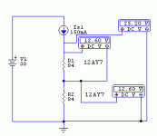
As you can see on the above simulations, when nominal current runs through the 6.3V configured heaters, each one develops 6.3V across. One sits on top of another 6.3V. So the upper point measures 12.6V respective to ground. It floats. If you run 600mA, they will go 12.6V each, will burn bright and die soon.
So what I suggested was to configure each 12AY7 for 6.3V and make a 317 300mA CCS to feed them in series. Then make a 365mA 317 CCS to feed the two ECC88 in series.
I suppose here you are assuming a nominal 12.6V supply. Correct?
No, I assume a 12V secondary, rectified and filtered with a large electrolytic. There can't exist 6.3V or 12.6V CCS. There is a 300mA and a 365mA CCS, powered by that supply. If you run through a parallel 12AY7 heater 300mA by force, it will develop 6.3V when it heats up well. If you string beneath it another one, still the same current passes to ground and it develops 6.3V across too. Now if you measure from top valve's heater to ground, it will be 12.6V total.
OK-- I'm about to push the button on a parts order and I have a request for some additional recommendations:
1. Tube sockets: I always use ceramic jobs and I've run into trouble over time with the contacts getting loose. I'd like to stay away from teflon as they're really expensive, but I wouldn't mind a recommendation on some nine-pin jobs that keep their contact integrity over time.
Also, would shielding the tubes make sense? I think it would for a phono stage, but I thought it would be worth asking.
2. Hook-up wire: Any recommendations here would be welcome. I like sold core wire (easier to work with) and I've used Alpha wire before, but if there's a better option out there, I'd like to hear it.
3. Rectification: Any recommendations on diodes here? I was planning on doing a solid state job with fast recovery diodes or Schottkys...
4. Pre-regulator smoothing: I was going to use a 220uF electrolytic as the first cap after rectification, followed by a 5H choke, then another 220uF just before the regulator. Comments on this?
Thanks in advance for answering these questions. This should be the final round before the order goes in.
Kofi
Kofi Annan said:OK-- I'm about to push the button on a parts order and I have a request for some additional recommendations:
2. Hook-up wire: Any recommendations here would be welcome. I like sold core wire (easier to work with) and I've used Alpha wire before, but if there's a better option out there, I'd like to hear it.
How about solid silver?
add to that teflon tubing from mcmaster (.09/ft) you're in business.
Kofi Annan said:Salas,
I'll order the original caps / RIAA resistor and the values you recommended as well. I can do a quick swap during listening tests to see which works better.
Kofi
Hello Kofi,
 This is a hot tip. If C1= 5700pF as in original, it is measurably waaay wrong. Don't know how it slipped, but it did.
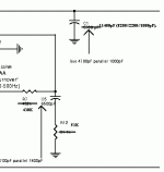
I made it easier to tune... I got to measure one known to be accurate RIAA and I overlaid the Bench RIAA on it by measurement again. So I left R7, R12, & C5 original, and I tweaked only one part, C1.
The two curves aligned, and the sound was spades better, when: R7=430K, R12=51K, C5=6500pF, C1=11400pF (8200//2200//1000pF).
Kofi Annan said:OK-- I'm about to push the button on a parts order and I have a request for some additional recommendations:
Also, would shielding the tubes make sense? I think it would for a phono stage, but I thought it would be worth asking.
Thanks in advance for answering these questions. This should be the final round before the order goes in.
Kofi
Yes, shielding caps proved not only just helping, but as the only solution to extra audible noise. A MUST get.
Also ONLY shielded coax for input and output hookup.
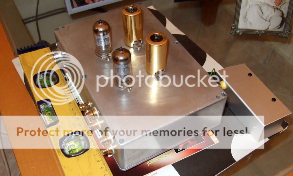
See the Bench with its shield caps on the 6072s.
salas said:
Yes, shielding caps proved not only just helping, but as the only solution to extra audible noise. A MUST get.
Also ONLY shielded coax for input and output hookup.
See the Bench with its shield caps on the 6072s.
Thanks!
I'm assuming you're shielding the two 12AY7s and not the 6DJ8s?
Kofi
In the particular build the noise susceptibility came from the 6072s. The 6N23P showed no change with caps or not. I would buy 4 caps if I was you, because you don't know what fields are gonna circulate in your build. Better have caps ready for all 4 valves.
Update:
Looks like my NOS 6N23P are OS 6N23P that have seen a couple of world wars and maybe a skirmish or two in Georgia. Of the eight I received, five are dead or very near it, one of which appears to have a short and three are only marginally usable.
I sent an E-mail to the seller, for whatever that's worth, and I'll try to order some more.
Jeez.
Kofi
I have all the parts together with the exception of the regulated filament supply as I have a question:
So, according to Salas' diagram I can use the LM317 as a current source. Since I have a 16V secondary that will rectify to about 22 - 23V it looked like I would need to drop it to 10V before feeding it into the rectifier according to the schematic.
I know that there's something I'm missing here, but does this mean that the regulator will always drop the same amount of voltage and keep the current constant? If so, how would I be able to best implement a 16V secondary that will feed four heaters, two with a .3A draw and two with either around a .3A draw or a .15A draw depending on heater wiring.
Salas-- I know you recommended a 4R2 resistor the .3A heater, but wouldn't I need to halve the resistor value if I'm feeding two .3A heaters in series.
Sorry to seem confused but I'm confused.
Kofi
As you can see in my examples higher on this page, you must specify the current at 0.3A and then feed one valve up on another in series. At their top they gonna reach 12.6V to ground, but 6.3V across each one. So if you feed the LM317V with 16Vin or 20Vin the margin down to 12.6V is more than adequate for it to work. Better with 18-20Vin. The 317 will heat for (Vin-Vout)*I. 1W for 16Vin, 2.22W for 20Vin. Better sink it anyway, so no worries. If this thing is puzzling, just use a couple of LM317s for 6.3V per channel, configured for voltage regulation as common. Make your phono, solve some more pressing issues maybe, and later you can experiment with Isource heaters, so you can appreciate it subjectively or not when you will be familiar enough IMHO.
Why make it complicated? I'd just go with a 6.3V supply and parallel all the tubes. In fact, I did: http://www.diyaudio.com/forums/showthread.php?postid=1061007#post1061007
You don't need the fancy filament lift, but I had the parts to do it. You will want to lift the filaments.
Sheldon
You don't need the fancy filament lift, but I had the parts to do it. You will want to lift the filaments.
Sheldon
I think Kofi's got it here...
So, one current source for the two 12AY7 heaters in series and another for the two 6DJ8s / 6N23P heaters in series. I'd need separate current sources as the current draw from the 12AY7 and the 6N23P would be a bit different.
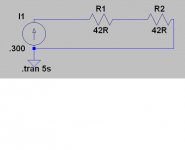
I can change the current supply by altering the resistor in the current regulator, but 12.6V will develop across each filament per Ohms Law with only say a .3A current draw due to the series chaining of the two tubes' heaters (see attached-- the 42R resistor represent the tube filaments in series).
I guess I'd have to be mindful that I'd need to change the current source if I change tube types (i.e., ECC88s for 6N23Ps) as I believe there are some current differences between the so-called "equivalent" tubes.
Is this right?
I could also use a trimpot or an Ohmite variable resistor or something here, couldn't I?
Kofi
So, one current source for the two 12AY7 heaters in series and another for the two 6DJ8s / 6N23P heaters in series. I'd need separate current sources as the current draw from the 12AY7 and the 6N23P would be a bit different.
I can change the current supply by altering the resistor in the current regulator, but 12.6V will develop across each filament per Ohms Law with only say a .3A current draw due to the series chaining of the two tubes' heaters (see attached-- the 42R resistor represent the tube filaments in series).
I guess I'd have to be mindful that I'd need to change the current source if I change tube types (i.e., ECC88s for 6N23Ps) as I believe there are some current differences between the so-called "equivalent" tubes.
Is this right?
I could also use a trimpot or an Ohmite variable resistor or something here, couldn't I?
Kofi
Attachments
I am afraid that you must configure each 12AY7 tube's heaters in parallel and tie each tube to another in series, because you will have headroom for only 12.6V total. With 0.3A that is. 6DJ8 will not allow any manipulation any way, pin 9 is screen.
Well, I could cut the current in half (.150A) and use the 12.6V here, right? I think that's what you meant, but I'm just checking.
- Status
- Not open for further replies.
- Home
- Amplifiers
- Tubes / Valves
- Kofi Annan in: "Cascodin' with Steve Bench's RIAA!"