With Klippel you can change this afterwards to any position you want.Or will we be able to specify midpoints at say tweeter or in between the tweeter and the woofer.
If I am not mistaken, points in between are being interpolated.
I assume with just some kind of average between.
I have to say that this is one of the main key elements of the system.
Because it means you don't have to measure everything again.
Well, where do you draw the practical line with this?And I have loudspeaker designs that are over 2 metres tall! So taller will be needed here. Most likely a bottom rolling support sled will be required. Even with a counterweight the distance required is not exactly small.
A line array that's almost as tall as a two story house most certainly won't fit.
In fact, I have my strong doubts that this method of measuring will even hold up so well in those cases.
Well this is where comparisons need to come into the picture.In fact, I have my strong doubts that this method of measuring will even hold up so well in those cases.
And truly the away from the baffle distance for a consultant is quite different from design to design. So having a horizontal arm long enough to accomodate different loudspeaker enclosures is going to take a little bit of thinking.
Erin Hardison what say you on whether Klippel can have a few mechanical improvements?
Last edited:
That is exactly what I am doingInstead of working with how many steps you have to take from/to each position, work with a coordinate grid system from a certain reference point.
Obviously under the hood it's the same, but it makes it just easier to work with.
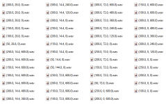
File naming is currently (radius, angle, height).wavIn that case also the (file) naming will be super straight forward, since you just have to see at what coordinate you are and what measurement had been done at the same time. (Either like really in time or what time in your loop).
Awesome!That is exactly what I am doing
That wasn't completely clear to me yet 🙂
Just an idea, but you could also also add a time stamp maybe?
In that case linking up measurements with coordinates might be a bit easier?
You want an arm that's at least 20 meters long? 😄😄Well this is where comparisons need to come into the picture.
And truly the away from the baffle distance for a consultant is quite different from design to design. So having a horizontal arm long enough to accomodate different loudspeaker enclosures is going to take a little bit of thinking.
Erin Hardison what say you on whether Klippel can have a few mechanical improvements?
If you make it larger, you probably need to make it stronger. At the moment it is good enough. The torsion of the vertical bar is the biggest problem. I had to change that to 2040 in order to be acceptable.So my take away points from your experience is that perhaps a little stronger profile? The counterweights being the determining factor?
At the moment it's just a plate with some holes. Could be made out of wood or metal easily.How is the creep deformation on the 3D printed parts? That will either be robust enough or start to slowly move around.
I think so. But longer arms -> larger moments -> stronger material -> heavier -> larger steppers -> CNC arduino shield current limit too low -> ...I see you have sized this perfectly for a small two way. Larger measurements are needed here.
So are these parameters easily adjusted?
To be able to do a true 1 meter measurement is still a requirement for almost everyone.
Everything is related and cost increases quickly. I think you can tweak it some more, but at some point you need another approach and/or different parts/solutions.
Last edited:
Timestamp could be added of course. Linking up measurements and coordinates is as easy as this:Just an idea, but you could also also add a time stamp maybe?
In that case linking up measurements with coordinates might be a bit easier?

But I'll add a naming convention layer so anyone can add their own way. "We can solve any problem by introducing an extra level of indirection" ("…except for the problem of too many levels of indirection,").
Last edited:
In this case I wasn't being silly about what fancy names people want, I am purely talking about keeping track of stuff to begin with 🙂ut I'll add a naming convention layer so anyone can add their own way.
This is not correct if the measurements are expanded in radiation modes, then interpolation is not required since the radiation modes are continuous. No averaging is required especially since averaging creates issues in and of itself. These are no longer issues with modal expansion. That's kind of the whole point.If I am not mistaken, points in between are being interpolated.
I assume with just some kind of average between.
I think I understand the confusion now. Motion control is in python, measurements are shown in REW. But...In that case also the (file) naming will be super straight forward, since you just have to see at what coordinate you are and what measurement had been done at the same time. (Either like really in time or what time in your loop).
I do both the motion control and the audio measurements in python.
def take_measurement_set(self):
        while not self._measurement_points.ready():
            position = self._measurement_points.next()

            if self._measurement_points.need_to_do_evasive_move():
                self._scanner.evasive_move_to(position)
            else:
                self._scanner.move_to(position)
            self._audio.measure_ir(po
sition)
No need to find the measurement as I have full control over it (s name). Output format is a wav file.
REW is just used as a viewer of the impulse responses in the WAV files. The octave post processing can also import WAV files.
Some interesting options in this video for a more heavy duty rig that can be broken down easily.
This is a great bunch of ideas. One of my clients makes very heavy cabinets. Rock! So something that can really hold some serious weight will be a great asset. Independent consulting can be an adventure!Some interesting options in this video for a more heavy duty rig that can be broken down easily.
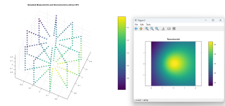
Sneak preview:
On the left the raw measurements.
On the righ a reconstructed sound field on the xy-plane
Low frequency:

You can see most of the sound is coming from the port.
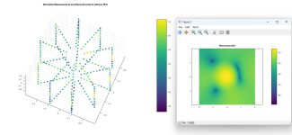
Mid Frequency:

🙂
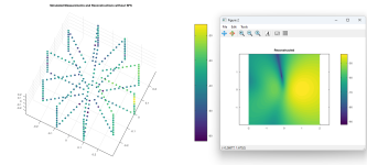
High Frequency:

Most sound from tweeter.
Not enough measurements, only one surface measured so no SFS, probably bugs, but we made some steps forward.
On the left the raw measurements.
On the righ a reconstructed sound field on the xy-plane
Low frequency:

You can see most of the sound is coming from the port.
Mid Frequency:

🙂
High Frequency:

Most sound from tweeter.
Not enough measurements, only one surface measured so no SFS, probably bugs, but we made some steps forward.
Last edited:
Directivity in real time! I can see this being of quite a large help in working out new ideas. And testing existing ones.
Would like to get this working for me as well at some point.
Right now my focus is on the Purification of my GAYA2 system.
But in that process i found some interesting points regarding baffle shape for the midrange i want to dive into as a next project.
Right now my focus is on the Purification of my GAYA2 system.
But in that process i found some interesting points regarding baffle shape for the midrange i want to dive into as a next project.
While recuperating from an very fine birthday party with some 50 people, i studied the klippel nfs from a mechanical point of view.
The construction concept is about stiffness without much acoustical reflection.
They made a quite stiff construction for the rotating beam .
Something to take into consideration as well i think.
Will ponder on that
The construction concept is about stiffness without much acoustical reflection.
They made a quite stiff construction for the rotating beam .
Something to take into consideration as well i think.
Will ponder on that
- Home
- Design & Build
- Software Tools
- Klippel Near Field Scanner on a Shoestring

