Keilau, you must just speak your truth and ignore the rudeness. Anyone who spends a lot of time here must be some sort of social misfit in my opinion. 😀
But, TBH, I have yet to hear a transmission line that excites me. The IMF TLS-80 with a KEF B139 was one of the dullest speakers I have ever heard.
No dynamics or presence whatsoever. It always sounded like it was playing in the next room.
Not excited by the IMF TLS-80? you must have a tin ear! 😉 Seriously, I cannot defend the IMF because I heard that only once a long time ago. But I was impressed enough that I decided to build a pair of TL woofer using Bailey's 1972 plan and the Philips AD10100 10" woofer. That was my first speaker project ever. Being a graduate student then, that was the best bass I could afford. The TL replaced a pair of Large Advent. The TL crossover to a Janszen Model 65 electrostatic panel at about 1000 Hz. The result was very satisfying in a small apartment living room. The fast transient of the TL woofer and the electrostatic upper were match made in heaven.
That was all so long ago when I was young and could move the almost 100 pounds TL enclosure without too much difficulty. 🙂
Last edited:
To be able to measure that low you would need a sizable anechic chamber…
dave
Measure outside on the soccer field - nothing easier than that. Results are better than any anechoic chamber.
Had TLs for about ten years now, never felt the need to replace them.😀 I do not use LHW but physics indicates that the propagation velocity of sound increases with the density of the medium.
Stuffing material would transform the acoustic energy generated behind the transducer turning it to heat and attenuate the sound to the point where it may seem to approach the acoustic level at the mouth for a much longer pipe. It would also absorb standing waves in a similar manner. Maybe natural materials such as wool performs better than synthesised material, but....
Claiming that LHW is less dense than air and therefore reduces the propagation velocity of the sound wave and in so doing increasing the apparent tube length, I don't think is likely.
I think that there are two very different approaches that can be followed with transmission line designs. The one is to design the line in such a way that it enforces certain frequencies at the port thus performing similarly to a bass reflex, and the other approach is to design it to attenuate and absorb as much signal in the tube, and performing as an infinite baffle. The first design approach would reveal the double impedance peak while the second will not (or much less of it).
I stand to be corrected.
Last edited:
The solution for you is very simple. Just stop reading any post with my name on it.
Hi,
I see that is the solution you use with anything you don't agree with.
rgds, sreten.
Had TLs for about ten years now, never felt the need to replace them.😀 I do not use LHW but physics indicates that the propagation velocity of sound increases with the density of the medium.
Stuffing material would transform the acoustic energy generated behind the transducer turning it to heat and attenuate the sound to the point where it may seem to approach the acoustic level at the mouth for a much longer pipe. It would also absorb standing waves in a similar manner. Maybe natural materials such as wool performs better than synthesised material, but.... .
The speed of sound increases with increase in density is true only in homogeneous material. A LFW filled tube is not homogeneous.
The adiabatic effect you tried to describe is NOT how the LFW work. Immediately after Arthur Bailey purblished his TL article in WW, a reader wrote to suggested that and showed some number to prove it. Bailey told him that it was the wrong physics.
http://p10hifi.net/TLS/downloads/bailey_letters.pdf
Claiming that LHW is less dense than air and therefore reduces the propagation velocity of the sound wave and in so doing increasing the apparent tube length, I don't think is likely.
I stand to be corrected.
Leslie Bradbury wrote a wonderful paper to describe how the LFW works. The LFW is dense (compared to polyester), stiff and larger in diameter. It forces the air to move around the fiber when the sound propogating in the TL tube. It is a fluid dynamics effect, not thermodynamics. You need to get a copy of the Bradbury paper to understand how LFW works. The paper includes both excellent formulation of equation and explanation of the theory. The reduction of sound was measured experimentally and matched the theory very well.
Where did you see that "Claiming that LHW is less dense than air and therefore reduces the propagation velocity of the sound wave"? Somebody misled you in how the transmission line enclosure worked. (A link?)
Can you show the impedance and frequency response curves of your speakers? If you use polyfill or similar, you get a vented resonant tube like Planet10 and other people on this thread said. You can call it TL, but..........
Measure outside on the soccer field - nothing easier than that. Results are better than any anechoic chamber.
I built the Bailey triangular tube enclosures. Each weights over 90 pounds. No, moving it will not be easy.
If you tried that (Measure outside on the soccer field) before, you will also find that it is not easy to find the windless day in the soccer field. 😡
Measure outside on the soccer field - nothing easier than that. Results are better than any anechoic chamber.
That would work. 1/2 space measurement should show the same roll-off rate… but the soccer guys are gonna be pissed at the hole you had to dig to bury the speaker.
dave
Leslie Bradbury wrote a wonderful paper to describe how the LFW works.
At least some of that here:Bradbury's Fiber Equations
dave
a vented resonant tube...
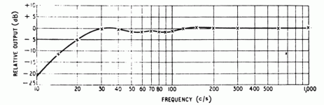
First, the FR published in Bailey's article:
On 1st approximation the roll-off is 12 dB/octave… 34 Hz at the start of the roll-off, down an estimated 24 dB at 8 Hz, 2 octaves lower. If we take the -3dB point as the knee of the filter (22 Hz) we can see it is down about 18 dB at 11 Hz.
A side-effect of this observation is that if keilau's line has a 1st order roll-off it is not a Bailey line.
A snippet from Bailey's article where he describes the fundemental of the quarter-wave resonance as the source of the bass enhancement.
dave
Attachments
Dave,
It is patternly unfair for you to point other reader to Martin King's website. After reading post #24 of this thread, you should know that Martin King copied the Bradbury equations incorrectly and did the calculation with the incorrect equations. The Martin King website is very different from the Bradbury paper.
It is mathematically impossible to go through the derivation from equation (3) to equations 4(a), 4(b) and 4(c) as posted by Martin King. I showed the correct 4(c) in post #24. You should be able to get the same calculation and plots as in the Bradbury paper instead of what Martin King showed in his website.
If you believe that I did the derivation incorrectly and Martin King was right, at least, you should show how the derivation should be done and point out my mistake. No, I mean Bradbury's mistake. It is just simple complex number theory and does not require solving partial differential equations.
It is patternly unfair for you to point other reader to Martin King's website.
And you do me a disservice to credit Martin with my web site.
That is a page from a TL designer that predates Martin King. His article is quite thorough -- i doubt he made mistakes in his Bradbury coverage -- and his speaker is quite good (at least according to those that have built them).
dave
I built the Bailey triangular tube enclosures. Each weights over 90 pounds. No, moving it will not be easy.
If you tried that (Measure outside on the soccer field) before, you will also find that it is not easy to find the windless day in the soccer field. 😡
Almost 100% of our days are windless, and lifting the speaker at least 1 wavelength of the ground using a hoist that runs up the flagpole is a lost cheaper than an anechoic chamber.
 All you need is permission from the club manager and your measuremenst is performed in free space.
But then what good is free space or anechoic chamber if they going to end up in some little 50 ft x 70 ft x 12 ft lounge filled with furnishings and stuff. 🙄
Thank God for headphones!
And you do me a disservice to credit Martin with my web site.
That is a page from a TL designer that predates Martin King. His article is quite thorough -- i doubt he made mistakes in his Bradbury coverage -- and his speaker is quite good (at least according to those that have built them).
dave
Dave,
Sorry about the mistaken identity. So you copied the incorrect equations and used them to do the calculations. Are you going to correct them in the near future?
What are you referring to when you said?
editor's note: the moving fiber hypotesis has been pretty much discredited, so take this with a grain of salt
Bradbury said that the long fiber wool was stiff and heavy enough not to move with the air, thus created the drag for air speed reduction. Bradbury's equations includes the fiber velocity term and showed that fiber velocity is very small compared to the air velocity in LFW filled tube. George Augspurger and Martin King both mentioned the fiber moving together with the air without showing any evidence, nor calculating the magnitude of fiber velocity.
Bradbury used what we call the "potential flow theory of fluid dynamics" to derive the "form drag" equation in fibe filled tube. The speed is small so that the viscous effect is ignored. There is momentum exchange between the air and fiber in the drag equations. The air is forced to move around the fiber to continue on, thus creating the air speed reduction. He showed test data (of both speed reduction and sound pressure attenuation) to validate that the equations work very well.
Last edited:
First, the FR published in Bailey's article:

On 1st approximation the roll-off is 12 dB/octave… 34 Hz at the start of the roll-off, down an estimated 24 dB at 8 Hz, 2 octaves lower. If we take the -3dB point as the knee of the filter (22 Hz) we can see it is down about 18 dB at 11 Hz.
A side-effect of this observation is that if keilau's line has a 1st order roll-off it is not a Bailey line.
A snippet from Bailey's article where he describes the fundemental of the quarter-wave resonance as the source of the bass enhancement.

dave
The KEF B139 is equivalent to a 10" woofer with the free air resonance at about 25 Hz. It is expected that the sound pressure output drop off rapidly below 25 Hz. It is basic physics, not matter what kind of enclosure box you use. It is unreasonable to expect the response NOT TO DROP-OFF FASTER below that.
The difference between a vented box and the Bailey TL is in the roll-off rate from 50 to 25 Hz. The Bailey design has a non-ringing bass because of this. On the contrary, a vented box such as the Martin King design will roll-off faster in this bass region.
Bailey credit the slow roll-off by re-inforcement from the terminus output. You yellow marked his statement.
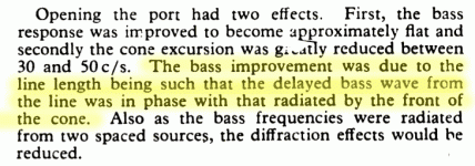
The bass improvement is due to line length being such that the delayed bass wave from the line was in phase with that radiated by the front of the cone.
I think that you understand that the line needs to be a half wave length to make the waves from front and back "in phase". With a quarter wave length line, they will be 90 degrees out of phase. There are still some re-inforcement at 90 degrees, but the result is nowhere as good as the half wave length. (Bradbury showed why the Bailey line was half wave analytically and it was beautiful modeling work.)
A polyester filled line is quarter wave because it offers NO reduction of airspeed to make the effective line length longer. Instead, it depends on the tube resonance for bass re-inforcement. Very different physics from the Bailey transmission line design.
Last edited:
So you copied the incorrect equations and used them to do the calculations. Are you going to correct them in the near future?
I published the article, the author wrote the text.
What are you referring to when you said?
Just what it days.
dave
The KEF B139 is equivalent to a 10" woofer with the free air resonance at about 25 Hz. It is expected that the sound pressure output drop off rapidly below 25 Hz. It is basic physics, not matter what kind of enclosure box you use.
But you were saying your box rolled off 6 dB/pctave. That means nelow 25 Hz. It should be flat above that (ideally, this are is dominted by the room). And we know you only measured to 50 Hz, so you have nothing but a guess as to the roll-off.
The difference between a vented box and the Bailey TL is in the roll-off rate from 50 to 25 Hz.
(assuning the extention is the sme) there should be no rolloff 25-50 Hz. 9 dB/octave.
On the contrary, a vented box such as the Martin King design will roll-off faster in this bass region.
Only if it is designed that way.
Bailey credit the slow roll-off by re-inforcement from the terminus output.
Yes, the fundemental of the 1/4 wave RESONANCE in the line.
I think that you understand that the line needs to be a half wave length to make the waves from front and back "in phase". With a quarter wave length line, they will be 90 degrees out of phase.
To be a half-wave resonator a line has to be open or closed at both ends. If open at one end andclosed at the other it is a quarter-wave resonator.
(Bradbury showed why the Bailey line was half wave analytically and it was beautiful modeling work.)
But we don't beleive Bradbury because when the rubber hits the road it does not work.
A polyester filled line is quarter wave because it offers NO reduction of airspeed to make the effective line length longer.
If we believed that damping made the line effectively lower then it would simply move the quarter-wave resonance lower -- or the line can be shorter for the same resonance. It turns out that this observed phenomenon is caused by a taper from large to small (at the terminus end) and nothing to do with damping.
dave
This is an open appeal to anyone who has knowledge of complex number mathematics.
Can you derive equations 4(a), 4(b) and 4(c) from equation 3 as post at this website?
Bradbury's Fiber Equations
After you try your derivation, compare your with mine in post #24 and report back here.
A huge thank you in advance.
Can you derive equations 4(a), 4(b) and 4(c) from equation 3 as post at this website?
Bradbury's Fiber Equations
After you try your derivation, compare your with mine in post #24 and report back here.
A huge thank you in advance.
Keilau, you have left most diyaudio.com folks trailing in the dust here with complex number theory. Which is actually quite ironic for a 200 year old piece of mathematics discovered by Cauchy. I mean, ancien, nest pas? 😀
Are we destined to forever live in the past?
The way to make progress with this is to look at an interesting thought experiment by the late, great Steen Duelund:
At some point the front wave must meet the back wave and either cancel or augment. If you contrive two equal rooms, the damped port could be in either, with opposite results. 😎
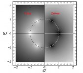
I no longer do algebraic mathematics. I really can't remember what an arctangent represents. Possibly group delay, but I've moved beyond that into geometry. The best representation of Cauchy's work is in the pole-zero notation (below). The image relates to third order butterworth filters. But it could be bass response.
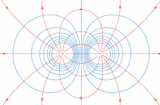
Now the Mobius transformation has everything I like about circle preserving conformal mapping (also below), spheres and planes and complex numbers.
https://www.youtube.com/watch?v=0z1fIsUNhO4
If you want to know how to move from algebra to geometry, it probably lies in Projective Geometry. And an equivalence between the two found in Ads/CFT correspondence.
The last image is just a fun bit of conformal mapping. It looks like a mirror, but in fact is a painting on a sphere outside a cafe in Ryde High Street, IOW.
We really should just enjoy the subject. IMO, the best place for the backwave of a speaker to go is outside the room. Why fight it? 🙂
Are we destined to forever live in the past?
The way to make progress with this is to look at an interesting thought experiment by the late, great Steen Duelund:
An externally hosted image should be here but it was not working when we last tested it.
At some point the front wave must meet the back wave and either cancel or augment. If you contrive two equal rooms, the damped port could be in either, with opposite results. 😎
I no longer do algebraic mathematics. I really can't remember what an arctangent represents. Possibly group delay, but I've moved beyond that into geometry. The best representation of Cauchy's work is in the pole-zero notation (below). The image relates to third order butterworth filters. But it could be bass response.
Now the Mobius transformation has everything I like about circle preserving conformal mapping (also below), spheres and planes and complex numbers.
https://www.youtube.com/watch?v=0z1fIsUNhO4
If you want to know how to move from algebra to geometry, it probably lies in Projective Geometry. And an equivalence between the two found in Ads/CFT correspondence.
The last image is just a fun bit of conformal mapping. It looks like a mirror, but in fact is a painting on a sphere outside a cafe in Ryde High Street, IOW.
We really should just enjoy the subject. IMO, the best place for the backwave of a speaker to go is outside the room. Why fight it? 🙂
Attachments

Keilau, you have left most diyaudio.com folks trailing in the dust here with complex number theory. Which is actually quite ironic for a 200 year old piece of mathematics discovered by Cauchy. I mean, ancien, nest pas? 😀
Are we destined to forever live in the past?
Good mathematics and good science does not change with time. In modern engineering, we still perform over 90% or our task using the even older (>400 years) Newtonian mechanics.
Yes, complex number is used only in invisid fluid dynamics. We have to use the partial differential equations of the Navior-Stokes for most fluid dynamics problems. Complex number is used a lot more in circuit analysis. Complex number is still the basic engineering tool and being taught as an integral part of today's advanced calculus and engineering mathematics curriculum. Today's engineers are NOT living in the past. mathematics evolves but does not discard the old.
Good engineering means using the most cost effective tools to achieve the tangible objective. The paper written by Leslie Bradbury is a good example of that. To see his elegant work being changed to meet a commercial agenda (that polyester fiber and long fiber wool work the same) is just not right. In both moral and technical sense.
I am not the scientist working on cutting edge mathematics. But you can Google my name with my company's to find the technical papers I wrote which would give you an idea of what I use in my day job.
IMO, the best place for the backwave of a speaker to go is outside the room. Why fight it?
I respectively disagree. A good engineer will no just throw away the perfectly good backwave. Arthur Bailey found an elegant way to use it and I like his approach and the resultant sound. Bass reflex is an alternate approach, but I am not attacted to the sound of a vented box. Air suspension gets the good sound, but pays the price in efficiency. OB is not the only way to go because we do not have the perfect woofer driver at reasonable cost yet.
Audio is just a hobby. You are right that I should just enjoy it. And I do.
Regards.
Last edited:
- Home
- Loudspeakers
- Multi-Way
- KEF B139b sp1044