I get a bunch of "undefined index" errors at the top of that page but I didn't find a KM board.
Ok, it's here:
Dirt Cheap Dirty Boards Keantoken K Multiplier
Enjoy, I hope all is right 🙂
If someone see something wrong shoot ASAP because I have some time to post corrections.
Dirt Cheap Dirty Boards Keantoken K Multiplier
Enjoy, I hope all is right 🙂
If someone see something wrong shoot ASAP because I have some time to post corrections.
"more info" takes us direct to the DIYaudio Thread.
The Multiplier PCB was right at the end of that very long pic list.
The Multiplier PCB was right at the end of that very long pic list.
I hope my 1,6mm white boards don't take 9 weeks to arrive 🙂
Heartfelt thanks sikahr for your efforts!
//
Heartfelt thanks sikahr for your efforts!
//
DirtyPCBs.com order #200xxxx status: Shipped
Cant take 8 weeks can it?
//
Earlier PCBs from Dirty, 3-4 weeks
Kuartlotron on 5x5?
Kuartlotron on 5x5?
Oh Yes that would be soooooo good! I'll take 20 or so.
Kuartlotron on 5x5?
Oh Yes that would be soooooo good! I'll take 20 or so.
Last edited:
Kuartlotron on 5x5?
Oh Yes that would be soooooo good! I'll take 20 or so.

http://www.diyaudio.com/forums/anal...or-correction-superbuffer-21.html#post4282268
Hi,
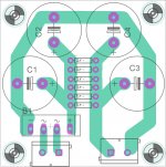
unregulated supply PCB, pi filter, needed before K mulitplier or superregulator, what do you think about layout (some parts are missing, snubers, bleeders ...)?
I tried to keep loops small.
Board is universal one positive or negative rail. Caps are 16mm diameter.
unregulated supply PCB, pi filter, needed before K mulitplier or superregulator, what do you think about layout (some parts are missing, snubers, bleeders ...)?
I tried to keep loops small.
Board is universal one positive or negative rail. Caps are 16mm diameter.
Attachments
Last edited:
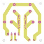
Your layout is not good.
The input to the first smoothing cap shares a link with the output from that first smoothing cap.
The OUTPUT must be on a separate trace from the INPUT to every pin on EVERY capacitor.
Follow the -ve trace, here you have separated the Input from the Output for every -ve pin.
The input to the first smoothing cap shares a link with the output from that first smoothing cap.
The OUTPUT must be on a separate trace from the INPUT to every pin on EVERY capacitor.
Follow the -ve trace, here you have separated the Input from the Output for every -ve pin.
Your layout is not good.
The input to the first smoothing cap shares a link with the output from that first smoothing cap.
The OUTPUT must be on a separate trace from the INPUT to every pin on EVERY capacitor.
Follow the -ve trace, here you have separated the Input from the Output for every -ve pin.
Like this? Top&bottom layers are the same.
Do you have suggestions for some additional components?
Attachments
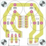
YES !!!!
now close up the loop areas.
Or use the two layer board to place one trace above/below the complementary trace.
Make the In/Out pads big enough to suit using ¼" spades that are soldered strongly on both sides of the PCB. Needs 4 extra holes compared to the terminals but preserve the pin pitch so that either spades, or terminals, can be used.
Is there room to add a snubber to the Input?
Last edited:
YES !!!!
1.
now close up the loop areas.
Or use the two layer board to place one trace above/below the complementary trace.
2.
Make the In/Out pads big enough to suit using ¼" spades that are soldered strongly on both sides of the PCB. Needs 4 extra holes compared to the terminals but preserve the pin pitch so that either spades, or terminals, can be used.
3.
Is there room to add a snubber to the Input?
1. Can you please better explain 😱
2. ¼" spades, have some pictures?
3. I.ll try to find place, resistor and cap serial at AC? how large footprint for cap?
push the +ve trace close to the -ve trace so that the gap between the two is very small = low loop area.1. Can you please better explain 😱
"faston" are another name for spade (male) and push-on terminal (female)2. ¼" spades, have some pictures?
quite small, try 0.1" and 0.2" pin pitch and make the 0.1" just close enough to allow a 1206 smd cap to be used between the pads.3. I.ll try to find place, resistor and cap serial at AC? how large footprint for cap?
Due to the capacitor blocking the DC and most of the 50/60Hz, the power dissipation in the resistor is very small. A standard ½W would do. The European 600mW are about the same size as ¼W and fit a 0.4" pin pitch. 0.45" is a nicer fit and saves bending the leads as close to the resistor body. Alternatively the resistor could be stood on end with a 0.1" pin pitch, but many Builders do not like this.
Last edited:
- Home
- Amplifiers
- Power Supplies
- Keantoken's CFP cap multiplier