Hi Keantoken,
Need your advice.
Does it make sense to install drain resistor in order to discharge all caps in my MOSFET headphone PSU when I turns it off?
I have analog voltmeter with LED illumination and its stays lighted for 5-7 min when I turn amp off. Not big issue, but I would like to try to fix that.
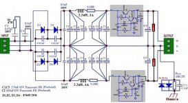
Please see attached schematics and correct me if the location is not right. Also, what would be the optimal value for that resistor - 10K?
Need your advice.
Does it make sense to install drain resistor in order to discharge all caps in my MOSFET headphone PSU when I turns it off?
I have analog voltmeter with LED illumination and its stays lighted for 5-7 min when I turn amp off. Not big issue, but I would like to try to fix that.
Please see attached schematics and correct me if the location is not right. Also, what would be the optimal value for that resistor - 10K?
Attachments

If you were to reduce the LED delay time to half it's current amount, then your PSU ripple would double, because you would need to double the idle load on the PSU.
Instead, I would suggest lighting the LED with a diode and capacitor across the trafo secondary, making the capacitor at least large enough that the LED does not visibly blink. This way there is no need to worsen ripple just because an LED stays on too long.
Instead, I would suggest lighting the LED with a diode and capacitor across the trafo secondary, making the capacitor at least large enough that the LED does not visibly blink. This way there is no need to worsen ripple just because an LED stays on too long.
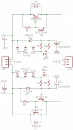
At that caes, I can use 120V AC of trany primery too. Please see first attached picture.
I'm not sure if I understood you correcly... Any dummy load increse ripple? So, if I'll remove both 10K resistors, then my Vripple will go down? Please see second picture. I marked 10K with red....
I'm not sure if I understood you correcly... Any dummy load increse ripple? So, if I'll remove both 10K resistors, then my Vripple will go down? Please see second picture. I marked 10K with red....
Attachments
Your top circuit will draw ~20mAac
i.e. ~28mApk through either diode.
That seems too much.
100nF or less seems more appropriate for a LED warning light.
Your bottom pic draws almost 17mAac.
But do you realise this is a direct to mains power project?
DIYaudio rules
i.e. ~28mApk through either diode.
That seems too much.
100nF or less seems more appropriate for a LED warning light.
Your bottom pic draws almost 17mAac.
But do you realise this is a direct to mains power project?
DIYaudio rules
Hi Andrew,
My blue led spec is 20mA max. Should be fine with 17mA on AC for 120V version.
What is DIYaudio rules about main?
My blue led spec is 20mA max. Should be fine with 17mA on AC for 120V version.
What is DIYaudio rules about main?
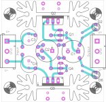
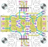
Got my + side working nicely but the - side oscillate at 26 Mhz, 100 mV. Please, what should I look for?
//
//
I have had an oscillation like that with slower TO220 transistors but not with the C5171/A1930. Do you know yours are genuine? In my case the solution was just to add a lytic right at the output, which I had forgotten.
OK - I had no capacitance on the output, only a resistor to get into the stipulated load. I'll check that out. Thanks!
//
//
Well it will not be soon because I managed to break the board with a compleatly stupid behaviour which I'm now contemplating... it'shard. And sadening.
🙁
//
🙁
//
One must point out that not just against diy rules but not legal in USA to put led on the mains as I understand it . It is must certainly as other have said is DANGEROUS . Do not do it please.
Sorry here on this post. #763At that caes, I can use 120V AC of trany primery too. Please see first attached picture.
I'm not sure if I understood you correcly... Any dummy load increse ripple? So, if I'll remove both 10K resistors, then my Vripple will go down? Please see second picture. I marked 10K with red....
One must point out that not just against diy rules but not legal in USA to put led on the mains as I understand it . It is must certainly as other have said is DANGEROUS . Do not do it please.
I see. Thank you.
I'll work with secondary of my trany.
24VAC is not in dangerous zone.
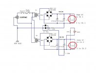
What the Difference Performance KM circuit here
Hi all,
Thanks to MR Keantoken for the circuit design
need to ask here, what is the Difference Result/Performance between those A and B circuit regarding KM regulator ? 😕

Any options to make it for let say :
1. Low voltage 12 volt, low current 20 -50mA only
2. High voltage 20-25 Volt, high current 3 - 10 Amp.
So we can choose the right Transistor and components value and avoiding any oscillations.
3. is it good to use Two positive circuit for Dual Rail supply + & - ?
4. Any disadvantage using positive circuit into Dual rail supply ?
Sorry too many Q
Thanks for any clue.
regards,
jc
Hi all,
Thanks to MR Keantoken for the circuit design
need to ask here, what is the Difference Result/Performance between those A and B circuit regarding KM regulator ? 😕
Any options to make it for let say :
1. Low voltage 12 volt, low current 20 -50mA only
2. High voltage 20-25 Volt, high current 3 - 10 Amp.
So we can choose the right Transistor and components value and avoiding any oscillations.
3. is it good to use Two positive circuit for Dual Rail supply + & - ?
4. Any disadvantage using positive circuit into Dual rail supply ?
Sorry too many Q
Thanks for any clue.
regards,
jc
Last edited:
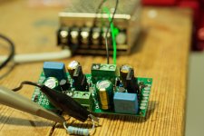
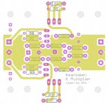
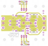
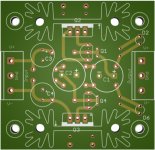
5x5 cm, at DirtyPCBs 14$ for 10 pieces, free shipping
Kean or someone else, please take a look is something wrong, thanks.
PS all high height element on top of the board, all low height element on bottom of the board
Kean or someone else, please take a look is something wrong, thanks.
PS all high height element on top of the board, all low height element on bottom of the board
Attachments
- Home
- Amplifiers
- Power Supplies
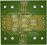
- Keantoken's CFP cap multiplier