10u-330u
Are you referring to the "stock" km ?
I am planning to use it before the 15000uf smoothing caps.
Or are you referring to the high voltage km Merlin is using ?
I am now building the k multiplier to feed my latest paradise build.
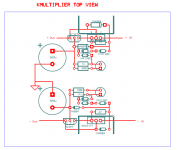
I am doing it by the book and just finished positive K.
I plan to use it in the psu just before the 15000uF smoothing caps..... Are there any issues I should be aware of because of the large caps ?
I am using 380 hfe BC337 and 327 because I did not have any 25 (only 40 leftovers from the paradise) hope it works as well.
Please have a look at my layout
Attachments
Last edited:
On my Kmultiplier webpage in my signature you'll see that I have a "design considerations" section. There is a simple equation there that describes how to size R8. Work that out and tell me what value of R8 you get.
Acording to your calc:
25,2 Vin-4.8 15000uF Cout
680 R8 940uF C1
0,037058824
37,0mA
15000/940 = 15,9
37 x 15.9 =591mA
I have 590mA
It is below 1A so I guess it is ok
25,2 Vin-4.8 15000uF Cout
680 R8 940uF C1
0,037058824
37,0mA
15000/940 = 15,9
37 x 15.9 =591mA
I have 590mA
It is below 1A so I guess it is ok
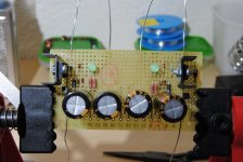
Just finished implementation.... it works perfectly and appart from lowering the noise floor it also provides a very usefull turn on time for the riaa amp.
Noise is much lower than my previous crc setup.
Sound wise it is also very good.... I notice an overall increase in detail retrieval and did not loose any of the "byte" I am already used to.
Thank you so much for sharing such a good schematic.
Noise is much lower than my previous crc setup.
Sound wise it is also very good.... I notice an overall increase in detail retrieval and did not loose any of the "byte" I am already used to.
Thank you so much for sharing such a good schematic.
Indeed... I followed my reasoning after reading your documents and although initially I was afraid I would loose some "snap" due to the extra filtering the final results proved my doubts to be unfounded.
The paradise keeps it's very good bass presentation while presenting much more detailed and fluid highs. (this also proves that the paradise shunts can surely be improved with better termination caps, because the circuit reflects whatever we have behind it).
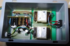
Now I will try the same circuit in my uber folded build.... (it will take a while because due to the kmultiplier vdrop I will need new 18V transformers).
In the folded case I already discovered the benefits from using a higher VA R-core tx and better smoothing caps.... will now see if it can be improved with your circuit.
You should be really proud 🙂
The paradise keeps it's very good bass presentation while presenting much more detailed and fluid highs. (this also proves that the paradise shunts can surely be improved with better termination caps, because the circuit reflects whatever we have behind it).
Now I will try the same circuit in my uber folded build.... (it will take a while because due to the kmultiplier vdrop I will need new 18V transformers).
In the folded case I already discovered the benefits from using a higher VA R-core tx and better smoothing caps.... will now see if it can be improved with your circuit.
You should be really proud 🙂

The closer a supply stays at steady DC, then the better a circuit performs.
For that reason I can never understand comments suggesting that performance deteriorates when larger capacitance is fitted.
For that reason I can never understand comments suggesting that performance deteriorates when larger capacitance is fitted.
I always wondered about this too. I know someone who says that core saturation causes larger banks to be able to draw less power from the transformer. Many people say that too large a reservoir bank sounds worse, but I can't find any reason why load regulation would decrease. I've been told it has to do with core saturation which is much worse for toroids. I can't find real measured data on the internet either way. I'm going to try and do some tests where that is concerned.
If charging pulses are higher and shorter then that will impinge on the quality of the DC that is delivered.I always wondered about this too. I know someone who says that core saturation causes larger banks to be able to draw less power from the transformer. Many people say that too large a reservoir bank sounds worse, but I can't find any reason why load regulation would decrease............
That is very easily improved.
rCRCRC or rCLCRC or rCLCLC all reduce the spike seen by the transformer and rectifier. Fast and soft rectifiers also give some advantages in minimising the HF that gets out of the charging circuit.
Any added resistance/inductance in the charging circuit reduces the height of the charging pulses and that must lengthen charging pulses. i.e. reduces the HF that can get past the smoothing.
I always wondered about this too. I know someone who says that core saturation causes larger banks to be able to draw less power from the transformer. Many people say that too large a reservoir bank sounds worse, but I can't find any reason why load regulation would decrease. I've been told it has to do with core saturation which is much worse for toroids. I can't find real measured data on the internet either way. I'm going to try and do some tests where that is concerned.
Sometimes you can see on the scope that the sine in a transformer is becoming a square wave: that means the core is saturated. The current is then maximum and can't go higher. so adding extra capacitance will just extend the flat top of the square wave, taking longer to load with the fixed output current.
This is why it is nice to use very very big transformers or use a resistor befiore the bridge.
Toroids have less leeway anyway.
- Home
- Amplifiers
- Power Supplies
- Keantoken's CFP cap multiplier