Freddi, regarding the X15, it's venting scheme seems to be fairly unique, with a single circular round hole at the top, a larger rectangular hole below, followed by 4 circular holes around the K-Tube. I was just thinking of somewhat more distributed venting for my TK6, perhaps with a resistive element, what do you think of this?
Here is an interesting take on the Karlson:
https://www.diyaudio.com/community/threads/acoustic-lens-on-a-full-range.373219/post-6682228
https://www.diyaudio.com/community/threads/acoustic-lens-on-a-full-range.373219/post-6682228
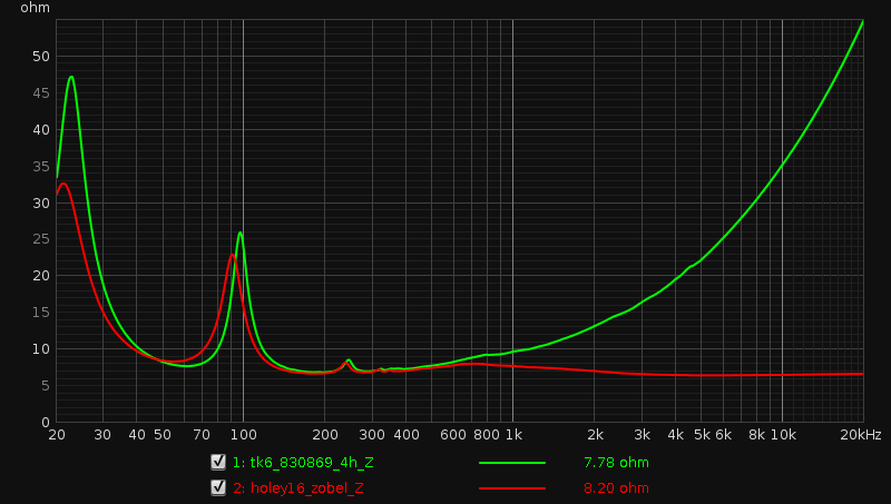
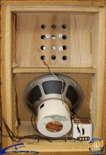
I tried my above proposed distributed vent, here are the results. The green traces are the TK6's previous venting scheme of 4x 1.5" holes at the top of the reflector panel, the red trace is the new scheme consisting of 16x 0.25" holes distributed in the reflector panel.
Picture:

Impedance, showing a resistive element introduced with the new vent:
Nearslot measurements:

Measurement at 25cm:
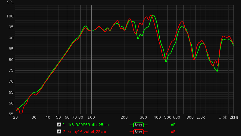
I'd say that worked out quite well. I just went for 16 holes not knowing how it would tune and it turned out a bit lower, but the LF response is hardly changed for that. The 200-400Hz region is improved and the 300Hz cavity resonance is 'tamed'. It also helps that the new driver, Peerless 830869 has a better low-end, making the 300Hz peak not as prominent. The 80Hz~400Hz cabinet bandwidth is pretty flat as Karlson go. The rollercoaster ride above this is hardly changed, not that I expected it to be. I'll have to see if anything can be done there as well.
This TK6 setup isn't Fullrange, but just a quick comment, it sounds much better than the previous 6FE100, FF125K or dual FF125K. I set up a K-Tube on in coming in at 3kHz. The subjective midrange coloration is noticeably lower than the other drivers despite similar response above the T/S+cabinet dominant region. The 15L rear chamber is too small for the 830869, but its low Qt allows for it and the bass sounds good, if not very deep. It's been some years, but I'd say it sounds about as good as the SK8 (K10-sized) with FF225WK.
Picture:
Impedance, showing a resistive element introduced with the new vent:
Nearslot measurements:
Measurement at 25cm:
I'd say that worked out quite well. I just went for 16 holes not knowing how it would tune and it turned out a bit lower, but the LF response is hardly changed for that. The 200-400Hz region is improved and the 300Hz cavity resonance is 'tamed'. It also helps that the new driver, Peerless 830869 has a better low-end, making the 300Hz peak not as prominent. The 80Hz~400Hz cabinet bandwidth is pretty flat as Karlson go. The rollercoaster ride above this is hardly changed, not that I expected it to be. I'll have to see if anything can be done there as well.
This TK6 setup isn't Fullrange, but just a quick comment, it sounds much better than the previous 6FE100, FF125K or dual FF125K. I set up a K-Tube on in coming in at 3kHz. The subjective midrange coloration is noticeably lower than the other drivers despite similar response above the T/S+cabinet dominant region. The 15L rear chamber is too small for the 830869, but its low Qt allows for it and the bass sounds good, if not very deep. It's been some years, but I'd say it sounds about as good as the SK8 (K10-sized) with FF225WK.
Nice work. You could try blocking vents to see if there is an optimum. If you can't make an improvement by blocking any vents, then that would suggest that more vents could be better.
keantoken,
I was going to write about my assumptions regarding blocking or adding vent holes as you suggest, but in the end, I think that the fact they are distributed and slightly resistive is what helps the most. Fb would naturally be affected in a predictable manner, but what it'll do to the areas with response anomalies, I could not say. I might test it out still.
I'd first like to see if anything can be done to reduce the magnitude of the 500Hz area notch. Notice that its exact frequency changes depending if I measure near-slot or at 25cm away. It also seems to have shifted between venting schemes, but perhaps the measurement positions differed enough to affect it? I don't know if I can look at the phase response in a meaningful manner to clue me in, as it is perhaps not possible to isolate driver and port output when the wings are on; their response is acoustically summed pretty much wherever I measure.
Cool work IG81 - I'm guessing if you feed the cabinet a sine wave at fb - there will be quite a bit of overtones from the little holes. Does some music stay in place long enough to cause audible effects? - transient material may aound better with a distributive vent. Karlson's X15 has been seen with a large vent like the later Acoiustic Control 115BK and choked down wih a plate with holes drilled. The late Martin Poppe said that Ann Karlson's X15 cabinet was tuned with 43- 3/8" diameter holes.
Karlson's later K12 kit has been seen with a blank panel and so with its assembly sheet. Missing must be instructions on what size and how many holes to drill for popular drivers of its day.
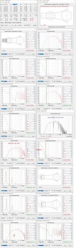
If you use hornresp, see if you can make sense of how to better compare a stub to no stub condition. This set of sims is for a little cabinet and the fudged-sim by MMJ
Oh - I'm in a hospital - was peeing a lot of blood - got to ditch a tumorous kidney
Karlson's later K12 kit has been seen with a blank panel and so with its assembly sheet. Missing must be instructions on what size and how many holes to drill for popular drivers of its day.
If you use hornresp, see if you can make sense of how to better compare a stub to no stub condition. This set of sims is for a little cabinet and the fudged-sim by MMJ
Oh - I'm in a hospital - was peeing a lot of blood - got to ditch a tumorous kidney
Attachments
Good luck freddi, I hope it goes well.
I suppose distributed vents could be used to target different standing waves inside a cavity?
I suppose distributed vents could be used to target different standing waves inside a cavity?
Last edited:
freddi,
Hope you recover and 2022 treats you well!
I might try some sort of QW absorber to see if I can get the front chamber even flatter, I don't know if it could help with either of the large nulls in the rear chamber.
I think going up to an 8" helped over 2x 4.5" or the 6" I previously tried. Perhaps a better "impedance match" to the front chamber and K-slot dimensions?
The above quote was from you in the "Karlson Compendium" thread. I was reading it yesterday and had lately been thinking of the same regarding the lower baffle tilt and shallower front chamber and increased height. I think the width should also not be much wider than the driver's nominal diameter, front chamber deepest point from wings ~0.5x nominal driver diameter. This is not really news, but the driver should be of low to mid Qt, the lower the Qt the lower Fs should be, as well as a fairly high compliance. The rear chamber should be undersized and tuned higher versus a max-flat alignment, for ~3dB hump in the mid-bass. Venting is what I was experimenting with now and I like the graph distributed small holes make at the very least.
Hope you recover and 2022 treats you well!
I might try some sort of QW absorber to see if I can get the front chamber even flatter, I don't know if it could help with either of the large nulls in the rear chamber.
I think going up to an 8" helped over 2x 4.5" or the 6" I previously tried. Perhaps a better "impedance match" to the front chamber and K-slot dimensions?
At K15's size and aspect, I think the front chamber should be made more shallow when the front shelf is deleted. Lets say lay the baffle back only 23 degrees rather than 30; make external height around 36 inches or so and have a curved upper reflector with K-tube and a compression driver.
The above quote was from you in the "Karlson Compendium" thread. I was reading it yesterday and had lately been thinking of the same regarding the lower baffle tilt and shallower front chamber and increased height. I think the width should also not be much wider than the driver's nominal diameter, front chamber deepest point from wings ~0.5x nominal driver diameter. This is not really news, but the driver should be of low to mid Qt, the lower the Qt the lower Fs should be, as well as a fairly high compliance. The rear chamber should be undersized and tuned higher versus a max-flat alignment, for ~3dB hump in the mid-bass. Venting is what I was experimenting with now and I like the graph distributed small holes make at the very least.
I suppose distributed vents could be used to target different standing waves inside a cavity?
It is what I was hoping for when changing over from the top vent. I previously had a notch, falling on the front chamber resonance luckily, from the rear wave cancellation I presumed. I went with distributed holes to create multiple pathways of differing length for the effect to be applied on a broader bandwidth with lesser magnitude. I think it worked to some extent.
Here's a measurement I posted earlier, still the 830869 woofer with distributed 'holey' venting, measured at 25cm, this time showing phase with minimum phase extracted - not that I pretend to really know what's going on there.

The phase response looks fair enough, even through the large peaks and dips. Noticeable is the large phase shift at ~1400Hz, not something that should be there for a single driver and no EQ or processing applied. I measure similar on my smaller XKi, but at a slightly higher frequency. It seems to correspond to the frequency where the SPL response gets back to that of the drive unit, IOW where the cabinet stop affecting the response. The shift is just so sudden, ~700deg (of excess phase) over a few hundred Hz. I would expect the front chamber to 'disappear' more gradually, as the wavelength gets shorter, so I don't know whether this is suggestive of that or something else.
The phase response looks fair enough, even through the large peaks and dips. Noticeable is the large phase shift at ~1400Hz, not something that should be there for a single driver and no EQ or processing applied. I measure similar on my smaller XKi, but at a slightly higher frequency. It seems to correspond to the frequency where the SPL response gets back to that of the drive unit, IOW where the cabinet stop affecting the response. The shift is just so sudden, ~700deg (of excess phase) over a few hundred Hz. I would expect the front chamber to 'disappear' more gradually, as the wavelength gets shorter, so I don't know whether this is suggestive of that or something else.
The group delay or waterfall plot can be used to identify where the sound is coming from. It may involve playing with windowing and FFT settings. If you provide the REW file I can take a look.
There is a 19.1ms spike in group delay at ~1432Hz. I cannot seem to generate a waterfall, REW crashes when I try.
(Very lucky so far - lung and bone scans = negative --got to wait up to a month to see a surgeon todiscuss an operation plus no insurance as it rose beyond what could pay and still pay taxes)
Karlson's flat pack K12 apparently came with an un-drilled port panel. Two examples which appeared to be factory drilled (one for Tannoy Red-other for EV) were vented as so and likely tuned
around 60Hz. Why did Karlson return to a full width rear chamber shelf vs the split shelf in K12 introduced around 1956?
Attachments
keantoken, I re-installed REW and checked "use OpenGL", it now works! I'm not sure why I would have not checked it in the first place though. Thanks for the tip!
freddi, I don't think the choke area created by the split shelf must have done much, so perhaps to simplify the parts/cut list in flat packs? Hang in there!
freddi, I don't think the choke area created by the split shelf must have done much, so perhaps to simplify the parts/cut list in flat packs? Hang in there!
The reflections evident in the REW file are very close in and hard to resolve. Here's an idea. Do a measurement with and without the aperture (without disturbing the mic or speaker) and then we can subtract one measurement from the other, leaving only the difference caused by the aperture. You can even view the impulse response of the difference, provided your measurements are time aligned.
I did just that this morning. Measured at 25cm, mic did not move, though I moved the speaker to remove the wings, but placed it back within 1-2mm. I don't believe I time-aligned, as I did not yet look into how to do it in REW.
With aperture:

Without aperture:

Aperture minus no-aperture:

All on the same graph:

I don't think the subtracted impulse response makes sense, as I was not time-aligned.
With aperture:
Without aperture:
Aperture minus no-aperture:
All on the same graph:
I don't think the subtracted impulse response makes sense, as I was not time-aligned.
- Home
- Loudspeakers
- Full Range
- Karlson response peaks and dips