
the only disadvantage with my layout is that for any repairs you need to remove the front panel and rear panel then disconnect the various connectors
then you slide the chassis plate out.
This is why I made a test bench first .. so not a problem for me
The valve biasing is easy just remove the front panel and the bias potentiometers are accessible. but remember this is the 1st attempt at this layout ..
then you slide the chassis plate out.
This is why I made a test bench first .. so not a problem for me
The valve biasing is easy just remove the front panel and the bias potentiometers are accessible. but remember this is the 1st attempt at this layout ..
Last edited:
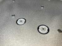
Hand made with hole punches and hole saws 👍 and cone cutters
but the aluminium blank I buy on eBay pre-cut to the dimensions that I need
I use a bare PCB as a template
I use a bare PCB as a template
will trial fit the chassis plate today .. as waiting for some fasteners (nuts & bolts) to be delivered
Bravo,my resspect.Fabriqué à la main avec des perforatrices, des scies cloches 👍 et des coupe-cônes
Hello
Just completed the bottom enclosure panel .. have mounted the 4 case feet (nice & chunky)


Just completed the bottom enclosure panel .. have mounted the 4 case feet (nice & chunky)
Hello
I have mounted the bottom panel last night with the enclosure feet attached .. so far so good
Just wish modushop would make a longer depth of this enclosure 450mm would be nice as the PCB depth is 350mm or a nice DIY valve enclosure with matching valve cage would be nice .. hint hint


I have mounted the bottom panel last night with the enclosure feet attached .. so far so good
Just wish modushop would make a longer depth of this enclosure 450mm would be nice as the PCB depth is 350mm or a nice DIY valve enclosure with matching valve cage would be nice .. hint hint
So this is the EL34 version (90w rms and the 1st 15w in class A)
Next I need to add the main power on/off switch and the stand-by pre heat switch ... plus drill the cats eyes out for thr power LEDs
slowly slowy catchy monkey .. hope it all works 🙄
Next I need to add the main power on/off switch and the stand-by pre heat switch ... plus drill the cats eyes out for thr power LEDs
slowly slowy catchy monkey .. hope it all works 🙄
Hello have just completed the front panel terminal connections
This is for the power on/off switch and the power stand by switch and cats led eyes


This is for the power on/off switch and the power stand by switch and cats led eyes
- Home
- Amplifiers
- Tubes / Valves
- K8011/K8010 PCB build thread