Hi Prasi,
Have you compared the sound of Nazar's regs with Juma's supply?
If you haven't sent your design off to the makers, could you perhaps alter the ground track where the diodes and cap then go directly to the output terminal Gnd and all the other ground connections are ended here but separately - this is just a small point but the idea is to keep the components that work with large currents (sec winding, diodes, power cap) away from those with the adjustment and reference points - don't know if it'll make any difference in use but better design practice - a bit surprised AndrewT hasn't mentioned this before as he's pretty keen on things like this
Hi Prasi,
Have you compared the sound of Nazar's regs with Juma's supply?
If you haven't sent your design off to the makers, could you perhaps alter the ground track where the diodes and cap then go directly to the output terminal Gnd and all the other ground connections are ended here but separately - this is just a small point but the idea is to keep the components that work with large currents (sec winding, diodes, power cap) away from those with the adjustment and reference points - don't know if it'll make any difference in use but better design practice - a bit surprised AndrewT hasn't mentioned this before as he's pretty keen on things like this
Hi James,
Thank you for your comments.
1. I have not compared Nazar regs with Juma's supply. I did ask Juma regarding PSU for this particular HA and he said any supply thats stiff and regulated would do well. So thats why I went with Nazar PSU.
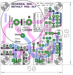
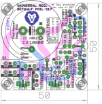
2. I havent sent the boards yet not until I am completely satisfied with layout. I am in process of laying-out a pos/ neg universal supply with Nazar design that I hope would be useful to people here. here is a draft.
Its a co incidence you mentioned grounding for LM based PSU, I had just read the Simple Voltage Regulators Part 2: Output Impedance
and I was doing a layout following the recommendations mentioned in the article. here is a screen shot . still a long way to go, but in right direction hopefully...
However, i feel that ground impedance in50x50 board with short and thick traces would be too small to have any effect.
reg
Prasi
Attachments
Last edited:
The second last sch shown with the correct (right) wiring is very important..................... I had just read the Simple Voltage Regulators Part 2: Output Impedance..................
This has been documented by others, probably going back more than 20years and yet it is ignored by most Builders.
The "node" philosophy adopted for the -ve output should also be followed for the +ve output.
i.e. the three attachments to the +ve output of the regulator should all coincide with the output pin.
Last edited:
There'll probably be some differences as the shunt o/p of Nazar's will have a different effect of the following stage and it'll be interesting to hear
Yes, as the tracks are quite short and the board is nice and compact, there's probably little advantage to get fussy over the ground tracking but sometime weird things happen - you could stretch R1 underneath so the solder pads are just on the edge of the big capacitor - run the track from the C(athode) of D1 across near D3 maybe - you could also mount D2 & D4 underneath to clear some space near the terminal block
I sometimes stack components on top of each other particularly if they have some common donuts, and sometimes top and bottom layers - no reason not to as the increased density can reduce tracking, etc - smd designs do it all the time, but it can get quite confusing!
All the best ...
thanks, what about the layout in post 122? does it meet the requirements?The second last sch shown with the correct (right) wiring is very important.
This has been documented by others, probably going back more than 20years and yet it is ignored by most Builders.
reg
prasi
Nice progress on universal PSU for headamps / preamps. I like the 3-4 pin option so legs don't have to be crossed on the regulator.
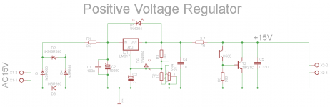
here is the sch and layout side-by-side, quite straight forward, tell me if you need clarification on any connection.I would need the sch and the layout.
It would help if the important nodes were labelled.
reg
prasi
Attachments

Last edited:
all thanks to AndrewT😉...Nice progress on universal PSU for headamps / preamps. I like the 3-4 pin option so legs don't have to be crossed on the regulator.
R5 should be rotated 90 degrees clockwise and it's feed should come direct from the output pin of the 317. NOT from the end of R3.
C4 pin2 should connect to the group of three pads (C3 pin-, Vrpin2 & Vrpin3) to make the -ve output node of the first regulator.
This node has to feed to the common node of R6, T2emitter,C5-, output
Note that R6 is directly connected to the last output node, NOT to the first regulator
This all goes wrong from the way we lazily draw the schematics.
We all take shortcuts and use that universal symbol GND for "ground"
They are NOT grounds. They are the other half of 2wire connections. Think through your sch and get the 2wire connections correct. stop using GND. keep your loop areas small. Allow the "stages" to work correctly, by getting the current routes in each stage correct.
Then join them together with 2wire connections.
Very compact nice design but why use dinosaurs LM317/LM337 and not LDO's ? LT3081/LT3091...
And why 2 asymmetrical PSU's when you need a symmetrical one ? Both a positive and negative one can be on one board and still be compact. Easier and less wiring too. Using 2 compact boards is nice and good but add the wiring and the benefit is gone.
It seems in fashion lately to make mono boards for stereo amplifiers and when PSU's are also split in 2 pieces that means there will be 4 (or even 6 when using separate PSU's) modules to wire up. I would like to understand what the benefits are as I don't see them. Those well designed compact PCB's will look like a jungle with all the wiring and it won't be compact anymore. Building costs are higher too with all those connectors. PCB manufacturing costs are also higher of separate boards. When imagining those 2 different situations it is not hard to see the difference in building the device and encasing it. Why choosing the hassle of wiring an external potentiometer with shielded wires when it can be on the board ? Just 6 pins to solder. I am not negative but I think it is way more handy to put effort in a complete design so builders all have easier reproduction of the device with less possible problems.
Amps and PSU on one board with all transistors on one side, pads for volume control and possibly pads for relays for input switching..... nah I'll stop fantasising. That would be way too few wiring and not enough work 🙂
Last edited:
Two input wires and two output wires to/from a regulated PSU. Both as twisted pairs.
What's the difficulty?
Small makes it possible to locate the PSU very close to the load.
What's the difficulty?
Small makes it possible to locate the PSU very close to the load.
Use imagination how it now is and how it could be.
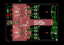
Recalled EUVL showed a teaser of his PCB ... Separate PSU's and transformers make it larger, it can be done smaller with just one PSU (if small is key parameter).
Edit: I added the picture of a multi board version form earlier in this thread for comparison. Please explain what the benefit is of using multiple boards.
Attachments
Last edited:
If a PCB design like that of EUVL is made with just one separate toroid/transformer and incoming supply lines tied together the board can roughly be one third smaller (or add muting relay + DC protection to protect that valuable cans, remote controlled volume control or whatever). Leaves more choice for the builders which transformer they want to use. IMO the most compact and neat looking, reliable and easy to build way of designing/building but I am prejudiced. Got promoted to chairman by the committee last week 😉
Less drilling and metal work, way easier mounting in a case without the need for a subchassis, no machine gunned bottom of the case but just a few mounting holes, almost no cable spaghetti so no antennas, short paths of signal (except inputs but that counts for both situations) and PSU lines, no 230V mains wiring prone to safety errors but PCB tracks/onboard fuse/possibly PCB mount IEC connector, easier accessibility for easier error finding or measuring, can be designed for a certain standard case to simplify reproduction by builders, power LED straight through front cover, volume potentiometer soldered and mounted straight through front cover, no "I am going to reuse this boards for something else" look. What is there not to like ?
Less drilling and metal work, way easier mounting in a case without the need for a subchassis, no machine gunned bottom of the case but just a few mounting holes, almost no cable spaghetti so no antennas, short paths of signal (except inputs but that counts for both situations) and PSU lines, no 230V mains wiring prone to safety errors but PCB tracks/onboard fuse/possibly PCB mount IEC connector, easier accessibility for easier error finding or measuring, can be designed for a certain standard case to simplify reproduction by builders, power LED straight through front cover, volume potentiometer soldered and mounted straight through front cover, no "I am going to reuse this boards for something else" look. What is there not to like ?
Last edited:
Use imagination how it now is and how it could be.
Recalled EUVL showed a teaser of his PCB ... Separate PSU's and transformers make it larger, it can be done smaller with just one PSU (if small is key parameter).
Edit: I added the picture of a multi board version form earlier in this thread for comparison. Please explain what the benefit is of using multiple boards.
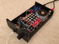
It's because the boards are small and separate that allowed me to stuff this class A amp into a much smaller case than what everyone uses. I used a basic $40 Breeze Audio case vs the much larger ones everyone else uses. The volume pot location was predrilled along with all IEC, RCA and headphone jack holes. If one had the foresight of knowing that this particular case was arranged a certain way one could make a single master PCB. But cost of small 50mm PCBs is $6 for 10. You should check what a 125mm x 165mm PCB costs to make. Anyhow, low cost and flexibility are the advantageous for the DIY'er. For a commercial product with know case a single board absolutely makes economic sense. Just look at inside of a Schiit amp or any other commercial product: 1 board.
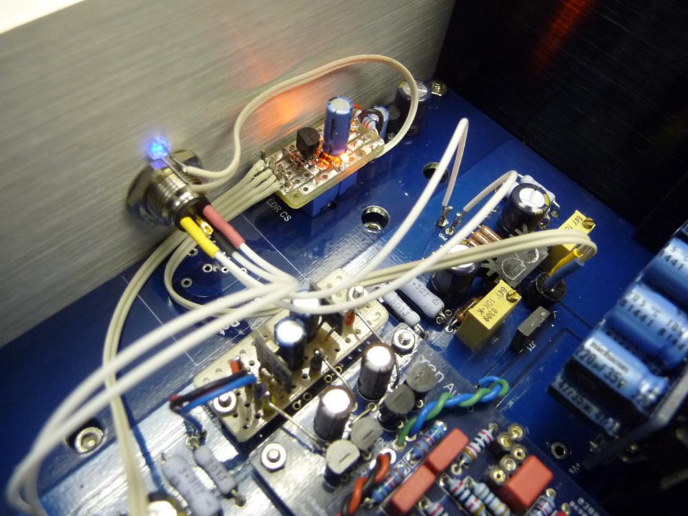
Here is another "single" board amp:
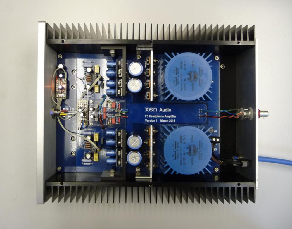
But closer look you see lots of smaller daughter boards on top of the mother board or even next to front panel:
That's a bigger case though.
Last edited:
Yup, that is a good example of a single board prototype (or first version) where mistakes are corrected and additions/changes are made to make a final version with all bells and whistles. It has been called "Version 1" which says the designer is not quickly satisfied and that improvements can be expected. Even in prototype state it is a nice build to look at. It shows a designer with care for details and maybe even a aesthetic and industrial way of looking at electronics. Something changed along the way and needed to be added in the least intrusive way. When the designer wants to add a potentiometer there is no problem as pads are already there. Pads are almost free. Flexibility !
My post wasn't meant as criticism on your particular build. I was comparing multiple board with single board setup in general but needed some specific pictures of this amp or similar amps. Surprisingly there are few counter points against single board setup.
If this way of working with multiple small boards is called flexible I must be doing something wrong 😀 Cost of one larger PCB can be lower than multiple boards. Please don't forget shipping costs etc. and the need to order more boards than you might like. I just gave EUVL board as an example but it can be made less wide and less long as said. I would not route input wiring that way I think. Even if a single board is more expensive you get something in return. Since DIY is almost always more expensive than buying ready built stuff one day wisdom arrives to build very good as it will be more expensive anyway. Build 10 cheap devices or build just one very nice version and improve possible shortcomings. What is less expensive and costs less time ? And: does it really matter if it is quality you are after ?
The 6P approach always works.
My post wasn't meant as criticism on your particular build. I was comparing multiple board with single board setup in general but needed some specific pictures of this amp or similar amps. Surprisingly there are few counter points against single board setup.
If this way of working with multiple small boards is called flexible I must be doing something wrong 😀 Cost of one larger PCB can be lower than multiple boards. Please don't forget shipping costs etc. and the need to order more boards than you might like. I just gave EUVL board as an example but it can be made less wide and less long as said. I would not route input wiring that way I think. Even if a single board is more expensive you get something in return. Since DIY is almost always more expensive than buying ready built stuff one day wisdom arrives to build very good as it will be more expensive anyway. Build 10 cheap devices or build just one very nice version and improve possible shortcomings. What is less expensive and costs less time ? And: does it really matter if it is quality you are after ?
If one had the foresight of knowing that this particular case was arranged a certain way one could make a single master PCB.
The 6P approach always works.
Last edited:
For a commercial product with known case a single board absolutely makes economic sense. Just look at inside of a Schiit amp or any other commercial product: 1 board.
Maybe we should look at it from reproduction/GB point of view. A good design may serve many builders. I have done a few large GB here and learnt some lessons. IMO a design must be well thought out before it is distributed. Of course mistakes are made, we are all human. Still thinking beforehand how builders will encase it etc is not a bad thing. I see some designs that don't have mounting holes for instance. How on earth should one mount such a PCB ? Melt glue ? Connectors on one side is also a nice one.
* Maybe it would be OK to make a DIY design protocol and choose default case sizes. Just an idea. Like with the stuff that is sold in the store here. It may sound stupid but that thought only now occurred to me. I never thought about it before but prices of the cases are OK and it makes designing easier. Predefine board sizes/outline and mounting hole pattern. Maybe even predefined purpose like "preamp" in a few board sizes so with predefined location of volume control and source control. Any new design would have the same mounting hole pattern and boards would be interchangeable so re-use of one the most expensive parts (the case) is guaranteed. For DAC boards and preamp boards this would work out I guess. Maybe the store can drilll all the holes according board purpose/type name, something many would like as metal work is like wiring: boring and prone to making errors.
So "preamp2" PCB would be larger than "preamp1" but volume control and source control are on predefined places in relation to the size of the case that is offered. Case can be drilled automatically in factory. Mounting holes AND holes in front. No volume and source control needed as it is a DAC you are building ? Just have all mounting holes drilled and don't put a check at "volume" and "source". User configurable so to speak.
If wiring mono amp boards and mono PSU boards is flexibility I don't want to be flexible 😉 Saves me from buying spools of cable and expensive Phoenix connectors too.
Last edited:
- Home
- Amplifiers
- Pass Labs
- Juma's Head Amp