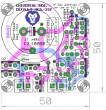
concept layout for universal positive/negative regulator. Default is for negative voltage. * marked components to be changed for positive voltage
1. either reverse orientation- caps and diodes
2. component change- BC550 to BC560, TIP31/41 to TIP32/42 LM337 to LM317
3. pin change - PIN 2 and 3 interchange for 317
comments anyone?
regards
Prasi
1. either reverse orientation- caps and diodes
2. component change- BC550 to BC560, TIP31/41 to TIP32/42 LM337 to LM317
3. pin change - PIN 2 and 3 interchange for 317
comments anyone?
regards
Prasi
Attachments
Last edited:
You mean physically cross legs 2/3 on LM317?
yes that's the idea.
I have done twisting legs quite a few times, not as bad as many would think.
My gut feeling is that positive rail is likely the most common use. It is probably the prefer default. To change gender, I think a step by step doc of how to will help others big time.
Once I receive my proto boards from DirtyPCB, I can experiment to use the LM337 and document the steps. After all, that's what proto boards are for🙂
I have done twisting legs quite a few times, not as bad as many would think.
My gut feeling is that positive rail is likely the most common use. It is probably the prefer default. To change gender, I think a step by step doc of how to will help others big time.
Once I receive my proto boards from DirtyPCB, I can experiment to use the LM337 and document the steps. After all, that's what proto boards are for🙂
Thanks Fred. That would be really nice addition to this thread.
I will try and make a universal board for the positive rail also later.
prasi
Also, isn't a positive rail board connected gnd to positive with another positive rail board going to do what we need? It's actually more balanced that way as the transistors are symmetric and identical.
Go ahead and use that if you are more comfortable😉. Fred will be having the boards soon and he will share here the dirtypcb link once he tests the boards.Also, isn't a positive rail board connected gnd to positive with another positive rail board going to do what we need? It's actually more balanced that way as the transistors are symmetric and identical.
I feel it is more convenient and simple to use dedicated pos and neg rail as one doesn't need to be extra careful with wiring 🙂. build the boards once and use it where ever you like with peace of mind!.
BTW I feel dirty PCB is a good source for protos as one can have red/white/blue/back PCB at no additional cost, 😎.
Unfortunately no, its better to use a 337 for the negative side.Oh that's really a cute board Prasi. Can two LM317 boards be put in series for a +/- supply?
Sent from my A0001 using Tapatalk
Its a headphn amp not a source, ie, a dac might benefit from better and cleaner supply, But i would argue that any line level unit should benefit from it.Is the LM317/337 noise figure OK for a Headphone amp ?
Is LT1083 a better option ?
Tks,
Eric
Sent from my A0001 using Tapatalk
You mean physically cross legs 2/3 on LM317?
better to use 4 pads for the two 317/337 options.yes that's the idea.
Hi Prasi,
What power rating you would recommend on the resisters ?
Other than R13 and R17, will 1/4W be sufficient ?
What power rating you would recommend on the resisters ?
Other than R13 and R17, will 1/4W be sufficient ?
Let say you bias the output to 150mA, then it will be 0.225W.Hi Prasi,
What power rating you would recommend on the resisters ?
Other than R13 and R17, will 1/4W be sufficient ?
Use the 3X or 4X rule, you want 1W.
If you plan to experiment higher bias, put a 2W there.
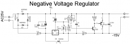
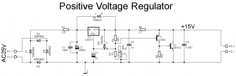
concept layout for universal positive/negative regulator. Default is for negative voltage. * marked components to be changed for positive voltage
1. either reverse orientation- caps and diodes
2. component change- BC550 to BC560, TIP31/41 to TIP32/42 LM337 to LM317
3. pin change - PIN 2 and 3 interchange for 317
comments anyone?
regards
Prasi
Nice layout Prasi.
My only comment if this PCB is intended as a +/-15Vdc supply for headphone would be to write lets say 15 or 18Vac instead of 25Vac. Ex : With the 25Vac you get a 35Vdc - 15Vout so 20V x bias, this get hot 🙁
Did some test of my own with some Jim's audio stuff while applying 25Vac with 15Vdc output and with 150mA bias my regulator were quite hot, if you intend to bolt the LM317/337 down to a metallic base then you're OK.
BR,
Eric
it has crept in my schematic since beginning based on the original schematic. http://www.diyaudio.com/forums/pass-labs/271926-f5-headamp-85.html#post4848402 . i will correct it. yes the intention is to mount the LM and TIP to the case / heatsink.Nice layout Prasi.
My only comment if this PCB is intended as a +/-15Vdc supply for headphone would be to write lets say 15 or 18Vac instead of 25Vac. Ex : With the 25Vac you get a 35Vdc - 15Vout so 20V x bias, this get hot 🙁
Did some test of my own with some Jim's audio stuff while applying 25Vac with 15Vdc output and with 150mA bias my regulator were quite hot, if you intend to bolt the LM317/337 down to a metallic base then you're OK.
BR,
Eric
reg
Prasi
based on the original schematic
The original schematic shows a value that was just as a number when simulating in LT Spice.
Thank you for your comment, like i said, i will correct it in my layout. BTW, nice site you have.The original schematic shows a value that was just as a number when simulating in LT Spice.
reg
Prasi
Last edited:
I will call this enhanced general purpose 3-pin reg PSU, and HA can be one application.
Preamp is another possibility. The best approach is to ignore the VAC and VDC silkscreen and work out the VAC for a particular application.
Let say the load draws a max of 300mA and requires X VDC output.
Then you can work backward to estimate the minimum VAC that is needed as following:
- 2.7R * 300mA => 0.81V drop., so you need X + 0.81 at the reg's output.
- If LM317 is used, it wants at least 3V between input and output => X + 3.81 VDC at input pin.
- The 3.3R will drop 0.3 * 3.3 VDC = 0.99VDC
- So roughly, VAC = (X+4.7) / 1.4.
- For X=15, you need 15VAC.
One thing to keep in mind, not all 15VAC transformers/toroids are equal. My Avel 30VA 15VACx2 actually gives 17VAC!!! To reduce the heat from the LM317, I changed the 3.3R to 4R.
For 15VDC, 18VAC is the max that I will use.
Hope this is useful.
yes, all resistors will be 0.25W except R13 and R17 which will be 1W like Fred said.Hi Prasi,
What power rating you would recommend on the resisters ?
Other than R13 and R17, will 1/4W be sufficient ?
reg
Prasi
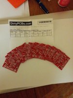
Just came back from Phoenix, Arizona and this on my desk 🙂
Unfortunately, I will have to travel to South California soon and will not have time to test this out until next week....
Nice, i like the red color!
- Home
- Amplifiers
- Pass Labs
- Juma's Head Amp