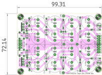
Small Cap Multiplier PCB by Prasi
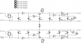
Here are the Gerbers for the small Mark Johnson/Gtose BJT cap multiplier by Prasi. Thank you, Prasi!
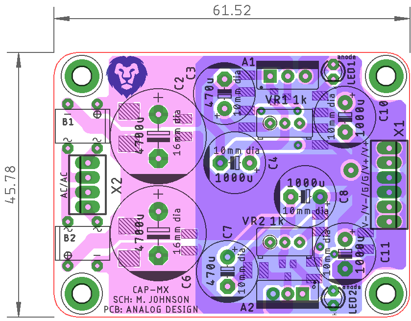
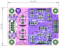
Design can use pinouts compatible with TO-220 using TIP41/42 and BC850/860 for SOT23’s. Small resistors are 1210 and 2512 for the cap bleed-off resistors.
Note that this is untested.
Here are the Gerbers for the small Mark Johnson/Gtose BJT cap multiplier by Prasi. Thank you, Prasi!
Design can use pinouts compatible with TO-220 using TIP41/42 and BC850/860 for SOT23’s. Small resistors are 1210 and 2512 for the cap bleed-off resistors.
Note that this is untested.
Attachments

Last edited:
Thanks Prasi and X
I actually like this one better with the cap on the output and the led.
Maybe I’ll order a batch, just what I needed for my headphone amps.
Thanks guys
Eric
I actually like this one better with the cap on the output and the led.
Maybe I’ll order a batch, just what I needed for my headphone amps.
Thanks guys
Eric
I actually like this one better with the cap on the output and the led.
Those, and the input bridges were my 2 cents worth of contribution to this board that Prasi made for use with HPA's. 🙂
Many thanks, Prasi and X
I'm a slow DIYer but I'll surely make use of this boards in the power supply of my next Preamp.
Compact and great design!
I'm a slow DIYer but I'll surely make use of this boards in the power supply of my next Preamp.
Compact and great design!
An update in the smd design...
The R1/R5 pads didnt have solder mask opening in the earlier gerber files as per post # 625.. it was brought to my notice by pcbway via the order placed by e_fortier.
Such great is their customer service and technical capability. They check each order very very carefully, no matter how small the order amount is.
Sorry for the omission, my mistake. So I am posting revised gerber files.
I have also added transformer snubbers for the ac, albeit its slightly cramped.
regards
Prasi
Attachments
Hi Prasi
Thanks a lot, I just send PCBWAY your revised Gerber.
First time soldering SMD, at least I’ll have a few pcb for practice.
BR
Eric
Thanks a lot, I just send PCBWAY your revised Gerber.
First time soldering SMD, at least I’ll have a few pcb for practice.
BR
Eric
You are welcome Eric...
Plan the soldering process carefully and you shouldn't face any problems.
Understand that there are few smds on top layer too and Under the THT components, so adjust accordingly for proper geometrical level of tht component.
All the best for your build.
Regards
Prasi
Plan the soldering process carefully and you shouldn't face any problems.
Understand that there are few smds on top layer too and Under the THT components, so adjust accordingly for proper geometrical level of tht component.
All the best for your build.
Regards
Prasi
Prasi, are we allowed to use the IXYS rectifier boards you designed - Or can I get you to design something similar?
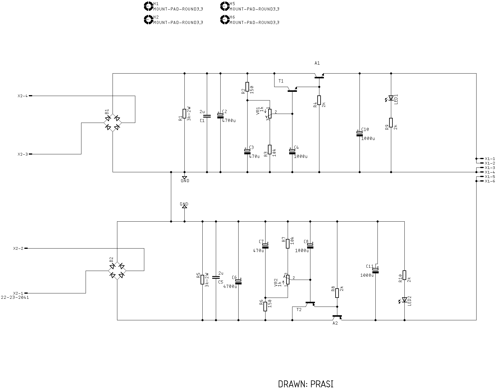
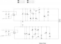
Be sure to check the emitters of T1 and T2 with an oscilloscope, looking for unwanted excess ripple when delivering the maximum permitted output current. This circuit's behavior gets worse and worse as you increase the output current, so: check it and double check it at MAX current.
You may need to adjust the values of R2 and R6 to find a compromise between (A: total voltage drop from in to out) and (B: ripple), that you can accept. Post #35 says more about this.
R2 = infinity gives the least ripple and the largest (total voltage drop from in to out)
R2 = zero gives the most ripple and the smallest (total voltage drop from in to out)
Thank you Mark for your suggestions.
As per the Juma's schematic , the values are 12k Ohm for the R2 and R6.
Also requires a regulated input for the circuit , so the on-board rectifiers + CRC may not be such a good idea.
Regards
Prasi
As per the Juma's schematic , the values are 12k Ohm for the R2 and R6.
Also requires a regulated input for the circuit , so the on-board rectifiers + CRC may not be such a good idea.
Regards
Prasi
Attachments
Hi Prasi
First.....congratulations for the great work
previously you mentioned that you were going to use the cap multiplier that you have beautifully developed for the Mofo powered with a SMPS.
I am in the same condition and I intend to adopt the result of your work. In a nutshell ..... introducing these cap multipliers have you noticed significant improvements in the sound?
Hi Sontero,
I think e_fortier/GTOSE is building the MOFO with smps and planning to use CMX if I remember correctly.
So its them who will be in a better position to share their experience.
Thanks for your enquiry and for your kind words.
regards
Prasi
I think e_fortier/GTOSE is building the MOFO with smps and planning to use CMX if I remember correctly.
So its them who will be in a better position to share their experience.
Thanks for your enquiry and for your kind words.
regards
Prasi
Hi Sontero,
I think e_fortier/GTOSE is building the MOFO with smps and planning to use CMX if I remember correctly
I wasn’t planning and won’t be using a CMX with the MoFo. The sound is great as is just w the SMPS.
Eric
I used the Juma MOSFET cap Mx with MoFo and it sounds great. I followed the cap Mx with a CRC using two 22mF and 0.22R resistors. 24v 5A SMPS feeding cap Mx. I think the Gtose cap Mx would be better as lower dropout to keep power output higher for MoFo.
Thanks XRK.
I currently use the SMPS simply followed by some polypropylene caps( around 700uF)
And I think the Mofo is an excellent amp.
My point is to understand whether to adopt the Gtose cap Mx (bjt version) downstream of the SMPS brings significant improvements and if a comparison was made?
I currently use the SMPS simply followed by some polypropylene caps( around 700uF)
And I think the Mofo is an excellent amp.
My point is to understand whether to adopt the Gtose cap Mx (bjt version) downstream of the SMPS brings significant improvements and if a comparison was made?
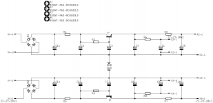
Biggest improvemt is lower dropout voltage so the BJT is more power efficient. However, you lose the nice 10 second long soft start voltage ramp up that prevents speaker turn on thump. The ripple reduction for both is about the same around -50dB. Jhofland has designed a new BJT version that uses a CFP (vs Darlington of the Gtose cap Mx) topology and should have even better ripple reduction performance and a slight 0.7 second ramp up time that just might be enough to prevent thump. I will be testing that design as soon as I order some test boards in the next few days.
CFP topology
Very good idea the CFP topology I think.
Jhofland has designed a new BJT version that uses a CFP (vs Darlington of the Gtose cap Mx) topology and should have even better ripple reduction performance...
Very good idea the CFP topology I think.
- Home
- Amplifiers
- Power Supplies
- Juma's Easy-Peasy Capacitance Multiplier