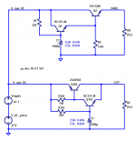
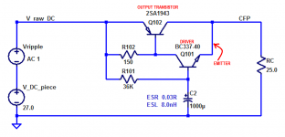
BJT version that uses a CFP (vs Darlington) topology and should have even better ripple reduction performance
BJT Sziklai pairs do have serious advantages over Darlingtons in some performance parameters, but unfortunately ripple reduction is not one of them.
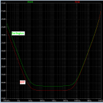
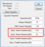
If you adjust R1 and R101 so the two circuits have the same in-to-out voltage drop {thus the same DC output voltage} then the CFP's attenuation at (2 x fmains), which goes by the name "ripple reduction", is only very slightly better. Don't forget to include realistic values of the capacitor parasitic ESR and ESL. Simulation below.
The problem is, both circuits have the series pass transistor's small signal output conductance (hybrid pi model parameter "ro") connected straight from input to output. It's a small signal resistance between emitter and collector, which in these two circuits means: straight from raw DC input to purified DC output.
One way to fix this is to connect two pass transistors in series, also known as Cascode. But cascode circuits cost extra in-to-out voltage drop.
Another way to fix this is to include a large amount of negative feedback in the circuit design, to actively sense the input-vs-output difference and nullify any ripple that might attempt to make an appearance. But NFB circuits require knowledge of control system stability theory AND knowledge of the output load including all bypass capacitors which are connected to the output pin. If the load is completely unknown, perhaps because that is somebody else's DIY project, 2000 miles away and 9 months into the future, stability might be difficult to guarantee.
_
Attachments

Thanks for running that sim, Mark Johnson. I think Jhofland had a different setup with the emitter of the driver connected to the output - I suppose this is negative feedback. Hence, your warnings about stability may come into effect.
Do you ever take a break, X? 😀
I have actually been battling a cold for past 2 weeks and not running anywhere near 100%, so sleeping full 8hrs vs usual 4hrs. So not getting that much DIY done vs my usual speed. But I sometimes have spurts of huge productivity (like everyone) and I try to get as many projects buttoned up as possible. The big push lately was Hugh's Deltic Class AB amp.
So now getting to enjoy it...
At least the speaker lab is sort of coming back to life (post basement flood), but with wood floor, and no carpet, it is a bit of an echo chamber.
... I think Jhofland had a different setup with the emitter of the driver connected to the output ...
sort of like this?
In a CFP the driver's collector is connected to big powerful Output Transistor's base.
_
Attachments
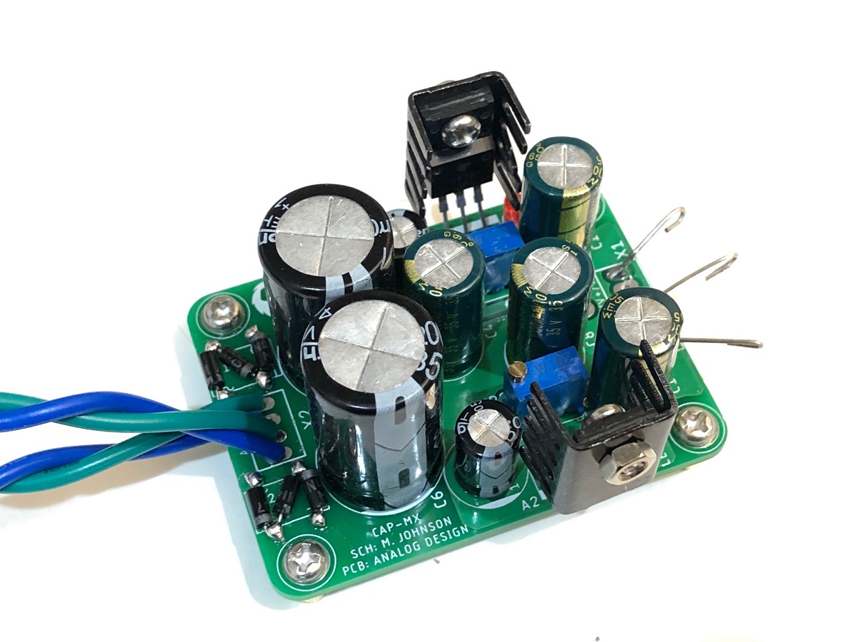
cap multiplier using bipolar CFP configuration
For those of you that are interested, here is the circuit that X was referring to. It includes two bridge rectifier inputs, one for the positive supply and one for the negative. There are two separate outputs for each supply. It uses surface mount devices except for the electrolytics, the bridges and the output devices. Total board area is 83mm by 100mm, exclusive of whatever means are used for heatsinking.
For those of you that are interested, here is the circuit that X was referring to. It includes two bridge rectifier inputs, one for the positive supply and one for the negative. There are two separate outputs for each supply. It uses surface mount devices except for the electrolytics, the bridges and the output devices. Total board area is 83mm by 100mm, exclusive of whatever means are used for heatsinking.
Attachments
Thank you for showing that schemetic, jhofland. It was fun to study.
One subcircuit that I found quite thought provoking, was the base-to-emitter network used for the output transistors, such as Q102. It's a standard, 1 ampere rated, silicon diode, connected in reverse bias, and nothing else. This diode is not a "fast recovery" type: its datasheet reverse recovery time is spec'd at 1800 nanoseconds --- unlike the corresponding diode (D111) across the driver transistor's (Q103) base-to-emitter, whose recovery time is 4 nanoseconds. An intriguing dissimilarity worth thinking about some more. The fact that base-to-emitter has a reverse biased diode and nothing else merits some additional thinking too. How does the base-to-emitter capacitance get charged and discharged, what are the pathway(s)? And other mental exercises of analysis.
Thanks so much for uploading it here!
_
Attachments

I think the 1N400x is simply a protection diode - disparity in recovery speeds is not an issue as it is usually in the off state.
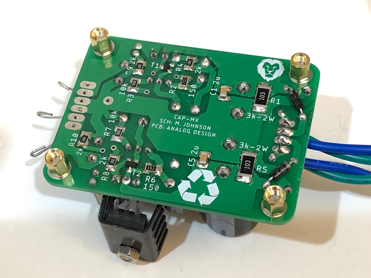
An update in the smd design...
The R1/R5 pads didnt have solder mask opening in the earlier gerber files as per post # 625.. it was brought to my notice by pcbway via the order placed by e_fortier.
Such great is their customer service and technical capability. They check each order very very carefully, no matter how small the order amount is.
Sorry for the omission, my mistake. So I am posting revised gerber files.
I have also added transformer snubbers for the ac, albeit its slightly cramped.
regards
Prasi
Hi Prasi,
I missed this post and ended up making the last version from JLCPCB. Not a big deal though. Do you have a part number for the little 4 pin bridge rectifier? I could just make one with 4 1n4007 diodes that I have on hand.
Thanks,
X
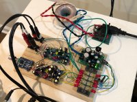
The little SMT BJT cap Mx works (not tested under load yet). Voltage drop is smoothly adjustable. I changed the LED resistor from 2k to 12k, otherwise burns too bright and not last very long. Using Antek AS2515 trafo. My homemade full wave bridge seems to have worked out well. I plan to use this to test some preamps and headphone amps now. The only TO220 BCE pinned BJTs that I have on hand are rare audio drivers 2SA1837 and 2SC4793. So a pretty upscale cap Mx. Will swap out with TIP 41/42 once I order them.
Thanks for sharing the nice layout, Prasi.

Thanks for sharing the nice layout, Prasi.
Attachments

Hi Prasi,
I missed this post and ended up making the last version from JLCPCB. Not a big deal though. Do you have a part number for the little 4 pin bridge rectifier? I could just make one with 4 1n4007 diodes that I have on hand.
Thanks,
X
Hi X,
Congratulations on yet another successful build.
The rectifier is https://www.mouser.in/datasheet/2/115/ds21201-87766.pdf
It can do 1A through it.
Your little homemade rectifier is quite innovative!
Regards
Prasi
Your little homemade rectifier is quite innovative!
Thanks, but nothing more than what a schematic shows for a full-wave bridge. Just aim the diodes from AC to DC in correct orientation (K to +ve). Putting one on the bottom side made some room though. These are also 1A diodes so about same performance.
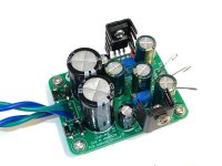
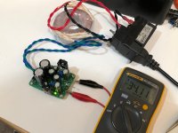
I am using the little BJT cap multiplier to power a pair of standalone Aksa Lender "Melbourne" preamo boards for the M2x. Here, is powering an ALPHA BB amp.
Works well - no audible hum in preamp. Sound of Melbourne is very nice and it makes a nice standalone preamp as well.
Works well - no audible hum in preamp. Sound of Melbourne is very nice and it makes a nice standalone preamp as well.
Attachments
I’m using two Cap-Mx from Prasi’s post in 497 in my M2C like X did. One transformer two sets of rectifier bridges for each channel. I’m have a problem with one of the channels and not sure the best way to troubleshoot.
When I first fired up the amp through my dimbulb tester the bulb lit and the CL-60 connected between the chassis growing and the Cap-Mx ground got really hot and there was a little smoke. I disconnected that Cap-Mx and fired the amp up again and after about 45 seconds the bulb dimly lit, not smoke. Pulled the Cap-Mx and checked everything. The only problem I could find was one lead on the 2SC5200 looked like it could have been touching the chassis. I fix that and replaced the board connected the chassis ground, not the amp, and fired it up without the other Cap-Mx connected. The bulb lit up. I lifted the chassis ground and fired the amp up again. This time the bulb did not light up and the voltages on the Cap-Mx looked good.
Not sure what else I should look at, parts I could try to replace to see if that fixes the problem. Any help is appreciated.
Brad
One transformer for two sets of rectifier bridges for each channel
This is a bit unclear - a diagram, maybe ….
Does this mean 1 transformer for each channel and then 1 rec bridge per secondary transformer winding and then 1 C-Mx per each bridge so the whole amp has = 2 transformers, 4 sec windings, 4 bridges, 4 C-Mx and quite possibly, one big earth loop.
This is a bit unclear - a diagram, maybe ….
Does this mean 1 transformer for each channel and then 1 rec bridge per secondary transformer winding and then 1 C-Mx per each bridge so the whole amp has = 2 transformers, 4 sec windings, 4 bridges, 4 C-Mx and quite possibly, one big earth loop.
I’m using two Cap-Mx from Prasi’s post in 497 in my M2C like X did. One transformer two sets of rectifier bridges for each channel. I’m have a problem with one of the channels and not sure the best way to troubleshoot. <snip>
Sounds like you might have a metal burr from ground on heatsink to metal tab of the BJT. Check your spacer insulator for pin holes. After assembling check with continuity meter to make sure collector and drain pins not conductive with ground.
Btw, I found that having two cap Mx connected in parallel to one set bridges is a lot less hum than two sets of bridge rectifiers. And then one set of bridges and one cap Mx shared by both channels is even less hum from ground loops. That’s what I am doing now, but in the end the best way is to have two transformers and separated dual monoblock power systems. I will order another transformer eventually.
Jhofland recently showed me an LTSpice simulation where a single transformer was connected to two sets bridge rectifiers (4 total) on two power supplies. The moment one load (side) is not perfectly balanced with the other, a residual difference appears between the grounds of each PSU. This causes ground loops and hum. Having separate transformers fixes this.
Last edited:
When I removed the Cap-Mx I checked to see if there were any burrs, but nothing. I’m thinking about building another board to replace to problem one and get panther transformer.
In the meantime I will look at running the amp off of one Cap-Mx.
In the meantime I will look at running the amp off of one Cap-Mx.
I suggest you have a close look at the F6 power supply diagram where there's 1 bridge per winding and one ripple (smoothing) cap per bridge then supplying the 2 output caps via 0.1R series resistors (hence 1 output cap for each channel per rail)
Replacing each output cap with a C-Mx will give you pretty much the same thing but with the better filtering of the C-Mx if you minimize the ground wiring
The big deal here is the SIMPLE, SHORT, CENTRAL power supply ground/zero volt system - no long wires from transformer, diode bridges, ground connections, etc - twisting the long wires doesn't substitute for short low impedance wires here - after using the long wires for initially getting it running is one thing but then simplifying the wiring is essential, especially the ground wire system - you need to get a bit fanatical about this part of the build - nothing 'slap-dash' or casual.
I tested the board again. This time I removed the screws holding the transistors to the baseplate and put a piece of cardboard in between. With the chassis ground connected the bulb did not light. I will have to look closer and see what is causing the short and make sure it does not happen again. I also ordered another 20v transformer and will run the amp dual mono.
What’s funny is I read somewhere Elsa on the forum about the same problem.
What’s funny is I read somewhere Elsa on the forum about the same problem.
I just built another SMT Mark Johnson/Prasi BJT cap Mx. This time I used BD139/140 and they work fine as they can handle 1.5amp max. I will be using under 300mA. They are ECB pinout so flip them around - it actually works well as heatsink fins fave out now. I am using 20v trafo and getting nice 24v output with 2v drop for lots of ripple regulation headroom. Nice thing is that I have lots of BD139/140.
- Home
- Amplifiers
- Power Supplies
- Juma's Easy-Peasy Capacitance Multiplier