Hi, here are some experiences ....
I have tested the PSU shortly. I used resistors of 24 ohms/50W, which then makes a current of more than 1.7A.
Positive channel with 50V input after rectifier -> 42.8 V at output. I measure a ripple of 0.3V !!! There is something wrong!
Negative channel 50V input -> 41.8V output. 0.000V ripple - not measurable, very nice. But overall, a high voltage drop in my opinion.
After 10 seconds one of the Chinese MUR820 exploded. So what - You get what you pay for. 😀
After the exchange against better things on the weekend I will measure again We have a really exciting hobby!
regards Olaf
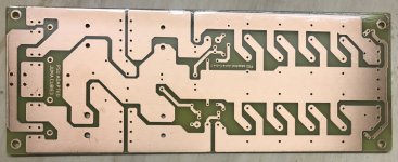
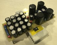
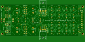
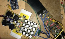
Hi, I have built a PSU free according to the Schematic which X has published in Post No. 95 with the parts I had on the shelf.
Will be tested next days or weekend. Looks good so far, not yet the optimal layout, but will developed. Just a few pictures for the entertainment 🙂
regards Olaf
Hi olafk
Would you be so kind to share the black and white with us , PDF is Ok.
Thank you 🙂 If you do not want to publish please send me a PM.
Greetings
The JUMA type one sided for iron, etc. transfer (you must resize it with your printer)
Attachments
Please wait a moment. It will be published when test is finished. See also post above.
regards Olaf
regards Olaf
Hi, here are some experiences ....
I have tested the PSU shortly. I used resistors of 24 ohms/50W, which then makes a current of more than 1.7A.
Positive channel with 50V input after rectifier -> 42.8 V at output. I measure a ripple of 0.3V !!! There is something wrong!
Negative channel 50V input -> 41.8V output. 0.000V ripple - not measurable, very nice. But overall, a high voltage drop in my opinion.
After 10 seconds one of the Chinese MUR820 exploded. So what - You get what you pay for. 😀
After the exchange against better things on the weekend I will measure again We have a really exciting hobby!
regards Olaf
Maybe it was the bad diode that made the ripple bad? I notice this circuit does not have a series resistor with 1uF at output as snubber. Try adding 2.2R or 4.7R in series with output 1uF to clean up any noise. The circuit in post 1 uses 10k and 220R - maybe try those values? But since negative rail worked, my guess is it was bad diode.
An 8V drop on neg rail, I guess comes
With the territory using a cap filter. Getting a higher V Torroid isn't that big of deal, when compared to performance.
With the territory using a cap filter. Getting a higher V Torroid isn't that big of deal, when compared to performance.
Very nice
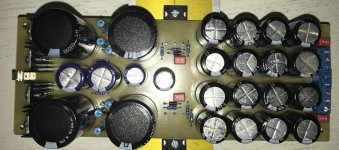
Hi, now I have built the second module with a few small changes. Great surprise - the measurements are the same (also AC on positive rail 😡). So everything with the Oszikkoskop checked - no AC 🙂 (will check my meter later). Soundcheck with an amplifier: Very nice! At least as good as with a regulated PSU (compared with Apex PSU for SR100), subjectively even better. Without a signal the loudspeaker is absolutely silent. No hum, no noise. 7 ... 8V drop is no problem with the result. I'm very satisfied.
Sprint file and PDF's will follow later.
regards Olaf
Attachments
Last edited:
Hi, now I have built the second module with a few small changes. Great surprise - the measurements are the same (also AC on positive rail😡). So everything with the Oszikkoskop checked - no AC 🙂. Soundcheck with an amplifier: Very nice! At least as good as with a regulated PSU (compared with Apex PSU for SR100), subjectively even better. Without a signal the loudspeaker is absolutely silent. No hum, no noise. 7 ... 8V drop is no problem with the result. I'm very satisfied.
Sprint file and PDF's will follow later.
regards Olaf
Very nice work Olafk! So for the record, what is the AC ripple in mV with load connected?
Last edited:
Hi, now I have built the second module with a few small changes. Great surprise - the measurements are the same (also AC on positive rail 😡). So everything with the Oszikkoskop checked - no AC 🙂 (will check my meter later). Soundcheck with an amplifier: Very nice! At least as good as with a regulated PSU (compared with Apex PSU for SR100), subjectively even better. Without a signal the loudspeaker is absolutely silent. No hum, no noise. 7 ... 8V drop is no problem with the result. I'm very satisfied.
Sprint file and PDF's will follow later.
regards Olaf
Nice work, if you don't use regulated PSU for amplifier I suggest cap multiplayer only for VAS like on SR150.1 schematic in post #1819 thread: http://www.diyaudio.com/forums/solid-state/173462-studio-reference-amplifier-182.html#post4198210
Regards
Hi Mile, yes, that's a good idea. I wil try this with one of your next amplifiers 🙂
regards Olaf
regards Olaf
So, here are some measurements (positive rail). With my transformer I measured a voltage of 48.7V behind the rectifier and a 42.8V output at load. That's 5.9V difference. Not as much as expected!
With a load resistor of 24V, 1.78A flow. That is much! With the oscilloscope I see a ripple of 7 mV. This is absolutely ok in my opinion. In any case, the 7 mV on the loudspeaker with the power nobody can hear 😀
regards Olaf
Image is Soundcheck with Apex FR50
With a load resistor of 24V, 1.78A flow. That is much! With the oscilloscope I see a ripple of 7 mV. This is absolutely ok in my opinion. In any case, the 7 mV on the loudspeaker with the power nobody can hear 😀
regards Olaf
Image is Soundcheck with Apex FR50
Attachments
is this measurement peak to peak, or peak, or ac equivalent?...............With the oscilloscope I see a ripple of 7 mV. ................
Thanks. 7mV is not much but interesting to see what ripple is at quiescent current (low volume ). Interestingly, the circuit on post one I had 33mF/0.25R/33mF and then cap multiplier with 4.7mF I got <1mV ripple at 1.3A load.
Again, peak to peak, or peak, or ac equivalent?.............. I got <1mV ripple at 1.3A load.
There's >9dB difference between the extremes.
Again, peak to peak, or peak, or ac equivalent?
There's >9dB difference between the extremes.
0.2mV AC on Fluke 101 so I round up to <1mV.
peak to peak in my opinion (not the expert), can later make photoAgain, peak to peak, or peak, or ac equivalent?
There's >9dB difference between the extremes.
Last edited:
Use of 2 N MOSFETs with close or matched Vgs for borh positive and negative rails let's you have a more symmetric voltage drops out of that is more important. Also lets you use N MOSFETs that typically cost less and are more one plentiful.
Having matched MOSFETs is not needed to make a cap multiplier though.
Having matched MOSFETs is not needed to make a cap multiplier though.
- Home
- Amplifiers
- Power Supplies
- Juma's Easy-Peasy Capacitance Multiplier