Mark,
There is a big difference with X's reg and the LM2941. IIRC the chips use a full on fb system with the output node at a collector; X's uses a darlington with no global feedback.
This is a small point, but I have found with audio that a global fb regulator sounds ordinary, while a compound emitter follower always sounds very good. This is not very scientific, but I suspect the reasons are the the emitter follower delivers a dropping Zout with increasing current, and a DC to light bandwidth. This is very different for the LM series, although they are well designed and impeccable at removing 60Hz ripple.
HD
Hugh, I'm just suggesting that the first N-1 stages of an N stage cascade (as proposed in post # 58), can be LDOs rather than cap multipliers. This gets you enormously greater ripple reduction which seems to be the main objective of post #58.
As for "DC to light" -- why not make a global feedback regulator using a truly excellent emitter follower transistor such as the ones you like, either Darlington or not, and then a video speed opamp whose GBW is much much greater than the emitter follower's fT ? The NSC LM7171 sells for 3 bucks and has a GBW of 200 MHz, which is much higher than any power BJT's fT. So the global feedback system is just as fast as the no feedback cap multiplier, AND it has drastically lower output impedance (thanks to NFB) AND it has drastically better Line Rejection / ripple rejection (thanks to NFB). What's not to like?
As for "DC to light" -- why not make a global feedback regulator using a truly excellent emitter follower transistor such as the ones you like, either Darlington or not, and then a video speed opamp whose GBW is much much greater than the emitter follower's fT ? The NSC LM7171 sells for 3 bucks and has a GBW of 200 MHz, which is much higher than any power BJT's fT. So the global feedback system is just as fast as the no feedback cap multiplier, AND it has drastically lower output impedance (thanks to NFB) AND it has drastically better Line Rejection / ripple rejection (thanks to NFB). What's not to like?
Member
Joined 2009
Paid Member
-- why not make a global feedback regulator
that's what I did in post #40
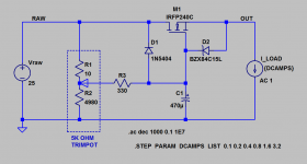
Isn't output impedance of the Juma cap multiplier given by the low Rdson of these MOSFETs? Preamps aside, for a power amp that draws 2 or 3 amps (or more) the IC's can't keep up. Don't get me wrong, I like using 7815's and 7915's when I can do happy to see another option. What surprised me is how quiet the cap multiplier is. Like an IC regulator but able to absorb huge ripples.
No.Isn't output impedance of the Juma cap multiplier given by the low Rdson of these MOSFETs?
Put it into simulation and measure Zout = dVout/dIout versus frequency. You'll find that Zout is quite a bit higher than Rdson. Change to a different MOSFET in simulation, another device with a very different Rdson; you'll find that a 10X change in Rdson produces much much less change in Zout. Whatever it is that controls Zout, it ain't Rdson.
This turns out to be a classic homework problem for 3rd year EE undergraduates: find the output impedance of an NMOS source follower operating at such-and-such current. After three or four pages of algebra the answer pops out and it has nothing to do with Rdson at all.
This is made obvious when you read the datasheet conditions under which Rdson is measured: very large Vgs and very small Vds. Neither of these conditions is found in a capacitance multiplier source follower circuit; the MOSFET never operates anywhere near the Rdson regime.
Thanks for the explanation. So what is it that controls the impedance? Does the MOSFET transconductance have anything to do with it?
that's what I did in post #40
And I made it 🙂 😎
Of course, my version.
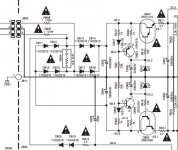
Many high quality Japanese amp used simple capacitance multiplier with CCS for zener to fix output voltage. Please see pic as below:
I tried simple capacitance multiplier with only 1 BJT tranny per rail, there is no any sound when hearing closed speaker cone but still available a little hum, buzz when i tested by earphone. So i want to find better circuits, anyone can suggest me?!
I tried simple capacitance multiplier with only 1 BJT tranny per rail, there is no any sound when hearing closed speaker cone but still available a little hum, buzz when i tested by earphone. So i want to find better circuits, anyone can suggest me?!
Attachments
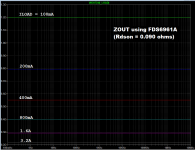
Here is one way to measure the output impedance of a capacitance multiplier circuit, in simulation: Zout = dVout/dIout. You use SPICE's AC analysis to perform small signal "incremental" analysis, then inject an AC "test current" into the output and measure the resulting voltage. Ohm's Law tells us that Zout = outputV/inputI. Easy.
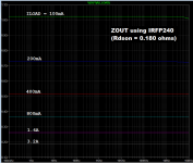
I ran it for two different MOSFETs whose Rdson values were different by a factor of two. As you can see, the MOSFET with the smaller Rdson had the larger Zout. Load current was varied around the post#1 centerline value of 1.5 amperes. As member AKSA pointed out, output impedance decreases when output current increases. This is why I like to connect resistors straight across the rails in low power audio circuits (preamps, DACs, line level accessories): the extra current lowers the power supply output impedance, and the cost (extra heat) is small.
_
Attachments
I will outline a few ideas here:If you have any experience with cap multipliers, please share. I have seen the ESP one and the one by Keantoken. This one with a single MOSFET is the easiest one I have seen though.
http://www.diyaudio.com/forums/power-supplies/298297-cap-mult-improvements-ideas.html#post4863361
Thank you Mark!
Wonderful, simple circuits to demonstrate a source follower for a power supply........
Much appreciated.
Hugh
Wonderful, simple circuits to demonstrate a source follower for a power supply........
Much appreciated.
Hugh
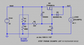
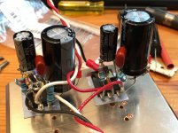
I redid my Juma cap multiplier with 50v caps and increased the 220uF to 470uF. 1N4007 diode and snubber is 4.7R vs 1.5R. Here are some closeups of the stereo setup on one heatsink.
With 44vdc rails input, I get about 39v output with about 400mA quiescent current. The ripple measured with AC volts is 0mV.
Currently using with my CFH9 amp.

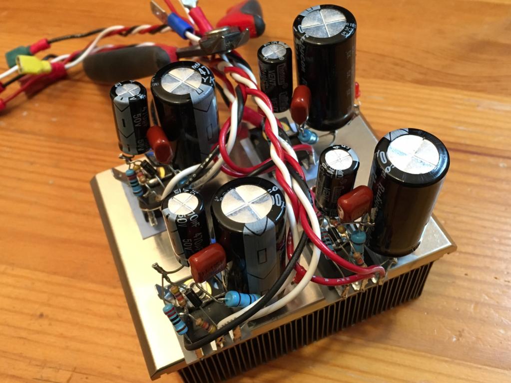
What's interesting is that it takes about a full minute to charge up to full voltage level - as if it is a huge cap.
With 44vdc rails input, I get about 39v output with about 400mA quiescent current. The ripple measured with AC volts is 0mV.
Currently using with my CFH9 amp.
What's interesting is that it takes about a full minute to charge up to full voltage level - as if it is a huge cap.
Attachments

The RC time constant determines the rate of charge build up.................
What's interesting is that it takes about a full minute to charge up to full voltage level - as if it is a huge cap.
Apply that slowly rising charge to the base/gate of the follower and you get a slow ramp up for the output voltage.
That's completely normal.
Typically 1k & 470uF gives (RC)=0.47seconds
5*RC gets you to nearly full voltage, i.e. 2.5seconds to full voltage, cf. 20 to 30ms for a typical capacitor input filter style PSU.
Hi X, I interested with this capacitance multiplier, very easy to build. But why use IRFP9140 for negative rail ? is it correct ? IRFP9240 or IRFP9140 ?
Can you post the schematic diagram as built?🙂
What is the max current to the load?
It's in post 1:

I changed the 220uF to 470uF, and the cap multiplier doesn't include the bridge and main smoothing caps, In my case it is CRCLC with 9600uF and paralleld 0.47R's and 0.56mH inductors upstream. It is designed for class A amp running at 1.5amps and I have used it there at 25v supply and works well (but with 33mF CRC where R is 0.125R).

The RC time constant determines the rate of charge build up.
Apply that slowly rising charge to the base/gate of the follower and you get a slow ramp up for the output voltage.
That's completely normal.
isnt goal of this device to charge like small cap it actualy is, but to discharge like big cap?
Hi X, I interested with this capacitance multiplier, very easy to build. But why use IRFP9140 for negative rail ? is it correct ? IRFP9240 or IRFP9140 ?
I use 9240. Any N and P ch MOSFET works. 610/9610 etc
The RC time constant determines the rate of charge build up.
Apply that slowly rising charge to the base/gate of the follower and you get a slow ramp up for the output voltage.
That's completely normal.
Typically 1k & 470uF gives (RC)=0.47seconds
5*RC gets you to nearly full voltage, i.e. 2.5seconds to full voltage, cf. 20 to 30ms for a typical capacitor input filter style PSU.
There is a 10k (4.7k x 2 actually) so maybe 25sec (is this 1/e definition?). I am talking about where value is 99% of final voltage.
Which capacitance is being multiplied? Is it more advantageous to use smaller value here so that gate of MOSFET can respond faster to current sags?
- Home
- Amplifiers
- Power Supplies
- Juma's Easy-Peasy Capacitance Multiplier