Not sure about how much room on the heatsink for all the different amp's using this variation of power supply but I think most would have enough, even if it's above or below the main amp pcb.
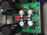
Oh your current design, you've achieved quite high component density by having the same rail power fets on each side of the board - ie. both +ve CMx filters are on the left-hand side as you look at the board and the 4 screw terminal allows connection to the left and right channels - nice piece of design that too
Oops, about separating just the mosfets off the main pcb presents a number of problems and most people that have tried this have ended up scrapping the idea - instead, move the complete CMx circuit itself to the heatsink but leave the diodes, main ripple filter electros, snubbers, etc next to the transformer
It's basically the same thing just divided up to fit on each channel's heatsinks
If we're again looking at current loads of about 1.5 - 3A, could use power fets with lower voltage drop like the IRFZ ones, the D44H11 ones, too - they're also TO-220 smaller size devices too
An example about layout - if the power fet devices are to be mounted on the main heatsink perhaps about 100 - 150mm apart, the pcb only has to be wide enough to support the secondary electros that don't need to be very big, like the output caps - I would keep the main filter caps right next door to the diodes, snubbers, etc close to the transformer, keeping all those high current pulses away from the active circuitry
I'm not sure if the idea of using 3 pcbs for a power supply (diode/filter brd, Right channel CMx, Left channel CMx) would be widely endorsed despite the advantages - it may appear too complicated - if designing the boards, maybe have it made as 1 piece with deep scoring so easy to break apart.
Quite a few guys have done pretty much this same thing with the rather neat/small K-Mx boards
Just some idle ruminations ...!
Actually, if you just used the first section of the CMx pair of the power fets M1 and M3, reduced the C2 & C10to something like 1000uF and re-arrange the components a bit, this would be a small compact one channel version that could mount on the main heatsink.
The diodes, main filter caps and so forth can be a reduced version of one of your established designs, or quite possibly a single block of diodes and a single pair of filter caps for a single raw +/- voltages
The perennial question of where to locate the amp's central 0 volt point suggests a couple of options
If on each of the CMx boards with maybe a separate CL-60 connection to chassis earth, or perhaps the single 'ground point' on the diode/filter cap board
I tend to favour moving each channel's CE point as far forward as possible (ie. on the heatsinked CMx boards) but perhaps other options can be provided
Thank you James for your suggestions.
I will be using a big 5u chassis.
The thinking was , plenty of space will be freed up in chassis, which otherwise would be occupied by bulky caps + cheap pcb + components ( which are significantly cheaper than capacitors).
Your suggestion of using different MOSFETs with lOwer Delta V gives me an idea , well worth a try. Can you suggest something in to-247 that are easy on the pocket.
Let my try it for my build and will post here.
Wondering, for class AB amp use, would this CMX followed by a crc board woulD be more suitable...
The CMx is better than just a replacement for the well built C-R-C or C-L-C power filter - it isn't a regulator, true, but it functions far better than the passive filters so you can spend the hard earned $s on better components - if you've got some excess room, can use the older larger caps that are much cheaper these days - I have a 'thing' about the older Siemens/Epcos filter caps, and the BHCs, etc, that are replaced by the smaller versions these days - it's the same with the American range of caps - perfectly good caps, just old (like me!)
For the power fets, you can't get much better than the ILZ24N/IRL9Z34N pair that aren't expensive - the AMB Laboratories regulator uses 2 each of these per rail (in //, sharing current with a 0.47R resistor) - this can be seen on the Sigma 22 regulator on their website - works like a charm in the simpler CMx too - voltage drop is about 2 volts across the device - there's quite a few of these devices around still altho more common as SMD that restricts device cooling and hence thru current.
Another one that's a favourite of Teddy Pardo is the pair D44H11/D45H11 - not so cheap - the original Super Teddy reg used these as a high gain CMx after a simple line regulator like the LM 78**/79** devices
These are both in the smaller TO-220 size and I think the pins are different to the IRFPs but very suitable candidates for design - pretty sure there are some substitutes for the IRFPs with lower voltage drop, but haven't used/tried any
The above examples are well-proven circuits/devices so don't need much experimenting - we tend to use the IRFPs because they're such well-known devices in the circuits we're familiar with and often are the 'outside limits' of matching pairs, etc
I've quite limited experience with Class AB amps - I am modding one of the Anthony Holton's AB amplifiers (2 of the older nxV200 modules) and will use your dual CMx after the big Epcos ripple caps, not the other way around - maybe it works better the way you're looking at it, but I've not tried it that way
A quite successful upgrade for the old Hafler DH220 amplifier (class AB) retained the single block bridge (upped the quality to IXYS) and 2 big caps (+/- rails) then added the simple CMx after that - a very simple successful upgrade that made a HUGE difference
you are welcome. nicely done. All the best for your build of Alpha amp with this CMX.
regards
Prasi
Greetings:
I may be remembering incorrectly, but I thought you had mentioned easyEDA as a layout program at one point. I just tried out laying out single power supply version and was disappointed in that all the parts are half sized (except for the MOSFET, for some reason). Any idea what I did? The big cap is a CP_10X25MM, but the leads are 5mm apart, and the circle is just under 12mm across. Any idea what I did wrong?
If I misremembered, or you don't use it much, does anyone else know anything about this particular issue? The search engines give me info on small circuit boards, not Lilliputian parts. Or should I get a better layout program? 8)
Sorry, can't help with easyEDA, but I did a layout for ACA boards with KiCad and it worked better than Eagle, which I had used before. I believe Eagle is now part of AutoDesk, and I must say KiCad is miles ahead of it. It even has a 3D viewer. I found that feature of KiCad very useful.
KiCad EDA is open source and cross-platform, and it's not going to cost you any money.
KiCad EDA is open source and cross-platform, and it's not going to cost you any money.
Greetings:
I may be remembering incorrectly, but I thought you had mentioned easyEDA as a layout program at one point. I just tried out laying out single power supply version and was disappointed in that all the parts are half sized (except for the MOSFET, for some reason). Any idea what I did? The big cap is a CP_10X25MM, but the leads are 5mm apart, and the circle is just under 12mm across. Any idea what I did wrong?
If I misremembered, or you don't use it much, does anyone else know anything about this particular issue? The search engines give me info on small circuit boards, not Lilliputian parts. Or should I get a better layout program? 8)
Hi,
I dont use easyeda for PCB design, I mostly use Eagle (99% of the times) and sometimes Sprint.
I have no idea what could have went wrong in your design with easy EDA.
I would recommend you to use any program with schematics checking ability.
I had only recommended easyEDA for manufacturing of PCBs as it was cheaper than PCBway. However easyeda no longer supports PCB manufacturing, they direct it to JLCpcb, which is now charging same as PCBway and higher price, if you choose any other color for masking except green..
So have shifted back to PCBway🙂.
regards
Prasi
I had a bit of a setback this evening. I applied power to the Juma E-P capMx and the pair of 3K 5watt resistors went up in smoke!
My test setup:
Trafo dual 20v secondaries->pair of BR254 bridge rectifiers->Juma capMx
Any thoughts?
My test setup:
Trafo dual 20v secondaries->pair of BR254 bridge rectifiers->Juma capMx
Any thoughts?
I had a bit of a setback this evening. I applied power to the Juma E-P capMx and the pair of 3K 5watt resistors went up in smoke!
My test setup:
Trafo dual 20v secondaries->pair of BR254 bridge rectifiers->Juma capMx
Any thoughts?
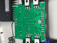
could you post some pics of top and bottom?
Hi Vunce,
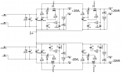
I do not see any mistakes with the build as such. It only handles about 0.3W at 20V. Check for any shorts and continuity between the joints/nodes. Could you recheck the bridge to rectifier connections. Here is the schematic for reference.
May be x can chip in as he has the same set up that he has been using.
regards
Prasi
Attachments
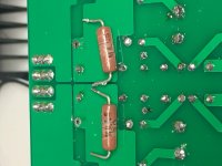
The 5W resistors are across the big 47mF caps are the capacitor discharge device and diode damping load, yes?
The photo shows "MILLS 30" on the lower resistor - perhaps they aren't actually 3kR but maybe 30R and that would sink about 13W
The photo shows "MILLS 30" on the lower resistor - perhaps they aren't actually 3kR but maybe 30R and that would sink about 13W
Those are bleeder res for caps so not essential to running. I myself use 6k8 here because I don’t like how hot 3k runs but it shouldn’t burn unless value too low. V^2/R dissipation of 3k and 28v is 0.26W so should be fine. Does everything else work though - 24v output and it slowly ramps up. Man, this board of your is built for bear! Stuffed to the max with premium caps and so glad those didn’t blow. I see you have Nichicon KA audio grade for the 200u that’s being “multiplied”. Those are great audio coupling caps I use on my Pocket amp.
Did you measure the Mills 30?
Did you measure the Mills 30?
The 5W resistors are across the big 47mF caps are the capacitor discharge device and diode damping load, yes?
The photo shows "MILLS 30" on the lower resistor - perhaps they aren't actually 3kR but maybe 30R and that would sink about 13W
eagle eyes


Hi,
I dont use easyeda for PCB design, I mostly use Eagle (99% of the times) and sometimes Sprint.
I have no idea what could have went wrong in your design with easy EDA.
I would recommend you to use any program with schematics checking ability.
I had only recommended easyEDA for manufacturing of PCBs as it was cheaper than PCBway. However easyeda no longer supports PCB manufacturing, they direct it to JLCpcb, which is now charging same as PCBway and higher price, if you choose any other color for masking except green..
So have shifted back to PCBway🙂.
regards
Prasi
Prasi - Thanks for the help. I tried Eagle, but got frustrated with it quickly. I imagine I'll learn eventually.
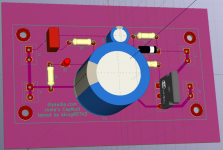
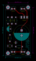
@Skylar88 - I tried KiCad, and with a little struggle ended up with a reasonable looking board.
My attempt at the CapMult is nowhere as compact as some here, but it's a single supply solution that fits 2 per 100mm sq boards.
- It has 1.5mm traces for the rails (and kept as short as I could manage).
- The traces for the 4700 are 1mm and the rest are 0.25mm. I have no idea if any of them are sufficient or not.
- The plan was to have bare copper on the bottom, silk screen on the top, and reinforce the power traces by soldering a bit of wire on top of the trace to increase the cross-sectional area (and therefore the power handling).
- I tried to leave a fair bit of space around the MOSFET so it could get a reasonable heat sink on it.
- the holes are just under 40mm across and just under 90mm on the long axis, so they should bolt into the standard 1cm grid.
- the big cap is way bigger than necessary, it has a 30mm diameter footprint, but better safe than sorry. I didn't check to see if the 30mm caps had larger lead spacing... I'll have to look into that.
- Any thoughts on the part layout or trace sizes/widths?
- I also could use some help figuring out how to officially mark the edge of the board (you can see that it's just in the silkscreen).
- Also, did I define the holes correctly?
- What other things can you spot that might need to be fixed before taking the plunge and getting some made?
Attachments
- I also could use some help figuring out how to officially mark the edge of the board (you can see that it's just in the silkscreen).
Looking good, Ken. 🙂
The edge of the board is drawn on the Edge.Cuts layer. Use a very thin line for that. You can also round the corners if you want.
Not sure I am going to do a GB here as these are handy boards to have so I am going to hoard all 10! 😀
Besides, you guys have the Gerbers like me - just order it from EasyEDA, PCBway, Seeedstudio, OSH Park, etc. $22 for 10 shipped to US. Prasi did a great service for us by making it all fit on 100mm square for big price discount.
Hi
Can somebody points out where can I get the Gerbers files?
Thanks
Fab
Fab,
See post #280. If you get some I wouldn't mind going in with you if you want to get some extras. I've tried submitting the gerbers myself but I aways end up getting some error messages from the board houses and I'm not smart enough to adjust the files to meet their requirements.
Steve.
See post #280. If you get some I wouldn't mind going in with you if you want to get some extras. I've tried submitting the gerbers myself but I aways end up getting some error messages from the board houses and I'm not smart enough to adjust the files to meet their requirements.
Steve.
Fab,
See post #280. If you get some I wouldn't mind going in with you if you want to get some extras. I've tried submitting the gerbers myself but I aways end up getting some error messages from the board houses and I'm not smart enough to adjust the files to meet their requirements.
Steve.
Thanks !
I had multiple pcbs done by a serious and not costly pcb manufacturer. My USSA5 amplifier pcb was made by Firstpcb and members who have seen the pcb are impressed with the quality.
No problem for some extra pcbs for you and you live also in Canada with no custom papers to prepare...🙂
1oz copper pcb is usually a lot cheaper than 2oz....what is your preference?
I will get the price for the 2 options.
Fab
Last edited:
- Home
- Amplifiers
- Power Supplies
- Juma's Easy-Peasy Capacitance Multiplier