Ok. which one would be a better?
1. CM+ CRC (CRC Power Supply (Class A amplifier))
2. CM+ Bulk cap (100W Ultimate Fidelity Amplifier)
3. CM+Bulk cap converted to CRC
If you are interested to build this one, I can make a quick mod to the bulk cap PCB to act as a CRC.. A number of 1W parallel 2512 SMD resistors will go on bottom to serve as CRC resistor...like the idea??
regards
Prasi
Last edited:
Hi Prasi,
I forgot all about the bulk cap bank you made. That would indeed be a neat approach. What is maximum capacitance one can expect for 50v rated caps on this board? 1000uF 50v caps are dirt cheap. So I am assuming it would become a 8mF / R / 8mF? 2200uF caps would bring that to 20mF / R / 20mF. I would go through hole 3W 0.22R if you have room for it. Those big SMT resistors are expensive.
But thinking about it more I think I am leaning to just an abbreviated Project16/Prasi layout as CRC would be what I think is useful as I know the board layout is very good.
Thanks,
X
😀Those big SMT resistors are expensive.
Thanks,
X
Free Shipping 100pcs 1R 1W SMD 2512 Resistor 1R 5% 2512 1W 1Ohm 2512 Resistors-in Resistors from Electronic Components & Supplies on Aliexpress.com | Alibaba Group
2200uF 50V with 16mm would be 13200u+R+13200u each rail.
I can fit 0.22R3W on bottom if you like it...
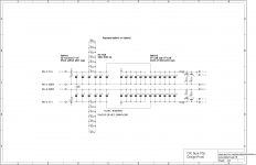
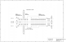
something along these lines...
The red outlined components mount from the bottom. One can take a pick between 2512's or a single TH resistor. I have used this technique of SMD CRC resistors and planes before and works like a charm.
I can keep Grounds of + and - rail separate if this PCB is used in conjunction with the Juma CM, as it has a star.
regards
Prasi
Attachments

This looks very good Prasi.
I think I would like the bulk cap bank ground connected ONLY at the output (lower ripple clean GND) side of the cap bank at the output spade terminals, otherwise unconnected upstream. It has to go to the amp as a common ground from the cap bank as the amp is only 1 GND wire. The sub 100mm dim makes it very cost effective too.
Thanks,
X
Nice work Prasi!
I just received today cap multiplier boards, really nice work, thanks! Anyone willing to share bom in .xls?
I just received today cap multiplier boards, really nice work, thanks! Anyone willing to share bom in .xls?
It's too simple to have BOM - as parts are all labeled on PCB.
Just run of the mill 1/4w resistors (1% or 5% metal thin film or carbon thin film) are fine except for bleeder 3k to 6k8 which needs tobe 2W to 3W.
qnty 4 of each:
10k
220R
1.5R (2.2R works too)
1uF 63v to 100v film (0.1uF works too)
1N400x (any will do)
220uF at rated voltage (35v to 50v is good)
4700uF at rated voltage (35v to 50v is good)
On input smoothing caps for bridge - as big as you can afford and fits. 22mF to 33mF (35v to 63v is good) should be plenty.
Input filter of 2.2uF filmcap 250v
Bleeder resistor qnty 2, 3k to 6k8 3W to 2W
Output needs 4 x 3mm LEDs and 4k7 to 15k resistors for LEDs.
Qnty 12 x 0.215in to 0.25in spade terminals (2 pin).
Qnty 2 IRFP240 (match identical Vgs on same sex if you can to get same voltage on both channels)
Qnty 2 IRFP9240 (match identical Vgs on same sex if you can to get same voltage on both channels)
That's about it.
Thanks X! I'm still going on the noob side of this hobby, everything you need to learn is written in english and my english isn't so good, especially tech words.
Thanks X! I'm still going on the noob side of this hobby, everything you need to learn is written in english and my english isn't so good, especially tech words.
Hi Juntuin,
ok,I understand the difficulty, as I have been through that. let me know your transformer specifications and I shall put together a mouser BOM for you.
regards
Prasi
Hi Juntuin,
ok,I understand the difficulty, as I have been through that. let me know your transformer specifications and I shall put together a mouser BOM for you.
regards
Prasi
Thanks Prasi, you are kind 🙂 I tried to collect some things, let's imagine 42v after rectifiers for example. Is there something really wrong?
(Led's are missing, spade connectors are too "thin" and you probs want to buy more IRFP's to match nice pairs?)
Mouser Electronics, Inc. Finland
Going to get eBay tester also, easier to match everything.
22mm and 25mm 6800u50V caps available
6800 uF 50 VDC Aluminium Electrolytic Capacitors - Leaded | Mouser India
with these it would be 20400uF+R+20400uF per side.
To x,
I have kept 3W/5W resistor on bottom side of PCB. This would need the resistor to be mounted at some distance from PCB as well as cabinet.
This in turn would mean using longer mounting spacers say 15mm.
dia of TH CRC resistor 6mm+ distance from PCB bottom 4mm+ distance from cabinet/chassis 4mm= 14mm.
Or better option is to use SMD 2512 1ohm 1W resistor, giving a total of 6W dissipation capability with equivalent resistance of 0.167ohm.
regarding your comment on connection of ground on output side, if there is an upstream Juma CM whose grounds are connected towards the output. How would that affect the working. would it make a loop between CM and CRC ?
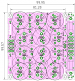
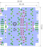
1st image is the view from top
2nd image is the view from bottom.
6800 uF 50 VDC Aluminium Electrolytic Capacitors - Leaded | Mouser India
with these it would be 20400uF+R+20400uF per side.
To x,
I have kept 3W/5W resistor on bottom side of PCB. This would need the resistor to be mounted at some distance from PCB as well as cabinet.
This in turn would mean using longer mounting spacers say 15mm.
dia of TH CRC resistor 6mm+ distance from PCB bottom 4mm+ distance from cabinet/chassis 4mm= 14mm.
Or better option is to use SMD 2512 1ohm 1W resistor, giving a total of 6W dissipation capability with equivalent resistance of 0.167ohm.
regarding your comment on connection of ground on output side, if there is an upstream Juma CM whose grounds are connected towards the output. How would that affect the working. would it make a loop between CM and CRC ?
1st image is the view from top
2nd image is the view from bottom.
Attachments
Last edited:
Nice work Prasi!
I like the SMT option - I have done that with a bunch of 0805’s in my amps for source resistors.
Let’s keep the grounds separate with provision for jumpers at either end to be provided by user depending on situation and appearance of ground loops.
I like the SMT option - I have done that with a bunch of 0805’s in my amps for source resistors.
Let’s keep the grounds separate with provision for jumpers at either end to be provided by user depending on situation and appearance of ground loops.
Thanks Prasi, you are kind 🙂 I tried to collect some things, let's imagine 42v after rectifiers for example. Is there something really wrong?
(Led's are missing, spade connectors are too "thin" and you probs want to buy more IRFP's to match nice pairs?)
Mouser Electronics, Inc. Finland
Going to get eBay tester also, easier to match everything.
ok, here you go. Hope this works
"
When you are ready to access your project again you can do so by using either of the following 2 methods:
1. Save the link listed below and enter that link into your web browser at anytime.
Mouser Electronics
2. Go to our Project and Basket Sharing page and enter your project Access Number listed below where you see Enter Your Access ID.
Enter Access ID: 46e41f83dc
"
For the 4700uF caps, I have chosen Wruth electronics part. If you feel its costly, choose anything thats 50V rated and 18mm dia x 7.5 mm pitch.
Also I had entered parts name designations against each components. But Mouser seems to be deleting the name designations..Funny
Last edited:
ok, here you go. Hope this works
"
When you are ready to access your project again you can do so by using either of the following 2 methods:
1. Save the link listed below and enter that link into your web browser at anytime.
Mouser Electronics
2. Go to our Project and Basket Sharing page and enter your project Access Number listed below where you see Enter Your Access ID.
Enter Access ID: 46e41f83dc
"
For the 4700uF caps, I have chosen Wruth electronics part. If you feel its costly, choose anything thats 50V rated and 18mm dia x 7.5 mm pitch.
Also I had entered parts name designations against each components. But Mouser seems to be deleting the name designations..Funny
Thank you very very much 🙂 can't complain the caps price tags, I think they are decently priced.
Thank you very very much 🙂 can't complain the caps price tags, I think they are decently priced.
My pleasure! and all the best for the build. please post your build here. It will motivate others for an affordable and easy peasy Juma CM for prospective amp builders.
To others,
Gerbers posted already, however someone not so comfortable with PCB manufacturing and ordering process, I can supply PCB or I can help with ordering process (As I have already done so for a couple of gentleman).
regards
Prasi
Thanks, I will!
PCB ordering was surprisingly easy, couple of clicks and you're done 🙂 with faster delivery PCB's came actually really fast, with reasonable cost.
Hi Prasi,
I ordered IRFP9140 Mosfets that were labeled on the schematic, but I see on your BOM you listed IRFP9240 Mosfets.
Are the IRFP9140's OK? Do I have to replace them with IRFP9240's?
Thanks,
Vunce
I ordered IRFP9140 Mosfets that were labeled on the schematic, but I see on your BOM you listed IRFP9240 Mosfets.
Are the IRFP9140's OK? Do I have to replace them with IRFP9240's?
Thanks,
Vunce
Hi Prasi,
I ordered IRFP9140 Mosfets that were labeled on the schematic, but I see on your BOM you listed IRFP9240 Mosfets.
Are the IRFP9140's OK? Do I have to replace them with IRFP9240's?
Thanks,
Vunce
Hi Vunce,
9140 are fine, no problems. like x said before in post #367 "match identical Vgs on same sex if you can to get same voltage on both channels"
regards
Prasi
So you are going to make something like this then??
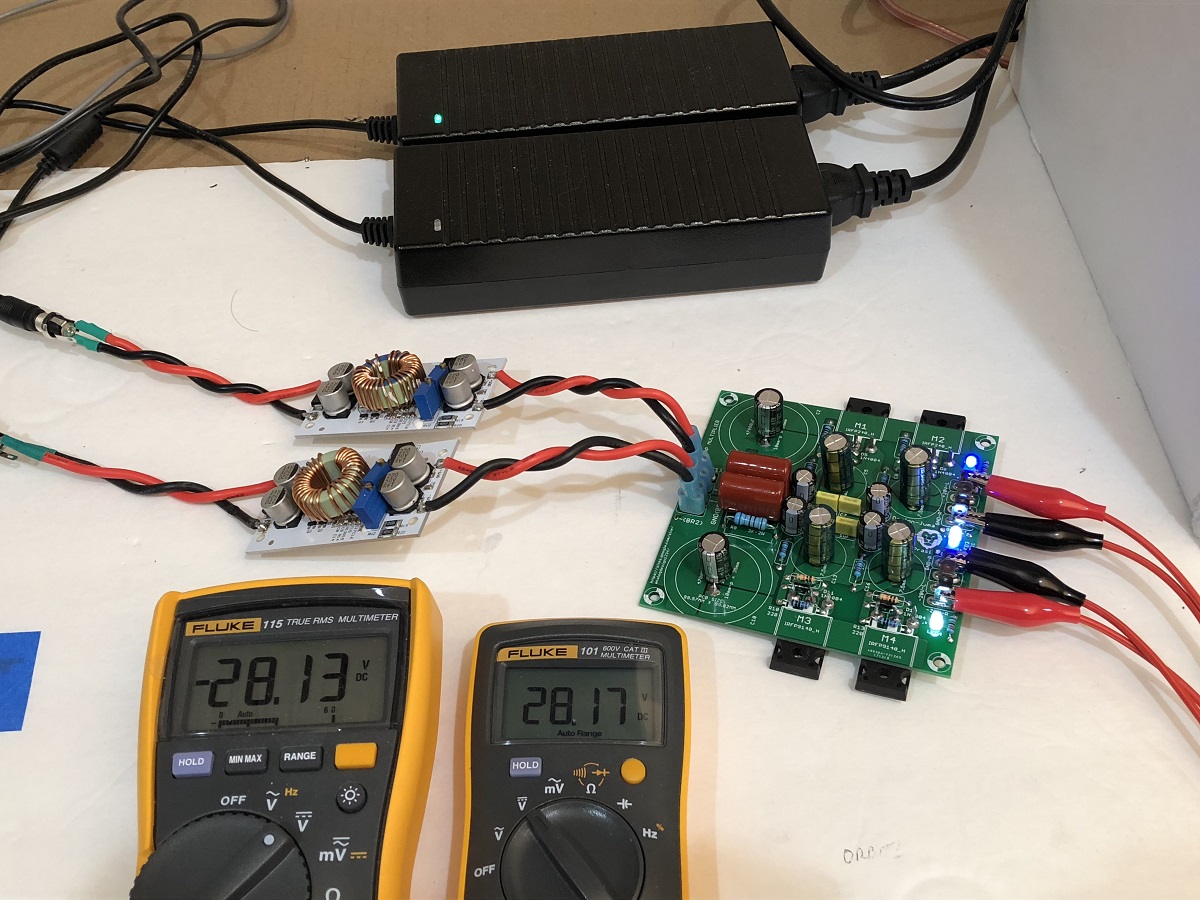
I’m gonna strip out the linear PSU in my ALPHA20 and put the SMPS and cap mx in tonight. Let’s see if it can handle 1.3amps and 28v or 24v and 2amps?
I’m gonna strip out the linear PSU in my ALPHA20 and put the SMPS and cap mx in tonight. Let’s see if it can handle 1.3amps and 28v or 24v and 2amps?
- Home
- Amplifiers
- Power Supplies
- Juma's Easy-Peasy Capacitance Multiplier