Hello, has anyone seen this design or made a simulation of it? I am interested especially in the MOSFET design, it seemed to share the same spirit as Juma's design.
Capacitance Multiplier Filter – PALADIN
Thanks!
Capacitance Multiplier Filter – PALADIN
Thanks!
It is not my design - it's very old and well known circuit, I saw it in somebody else's schematic more than 20 years ago and I use it and accommodate to different needs since then.... it seemed to share the same spirit as Juma's design...
That's not a good way to do it - that circuit doesn't have output cap (Source to GND) and the Drain to gate resistor is way too low.
Newby here, not totally understanding the finer points. I am assuming the cap multi is not voltage-in dependent. If one needs 5vdc then the DC input to the cap multi would need to be somewhere in the 8-9vdc range to compensate for the drop??
Tnx in advance
Tnx in advance
Thats ok Juma. We dont mind giving you the credit.
Like any good audio archaeologist, you did discover the find 🙂
Like any good audio archaeologist, you did discover the find 🙂
It is not my design - it's very old and well known circuit, I saw it in somebody else's schematic more than 20 years ago and I use it and accommodate to different needs since then.
That's not a good way to do it - that circuit doesn't have output cap (Source to GND) and the Drain to gate resistor is way too low.
If you do order some boards, could you add an extra 2 boards for me too?
Agreed...I MUST have a couple of boards of this Prasi layout as well.
PLEASE add me to the list.

Not sure I am going to do a GB here as these are handy boards to have so I am going to hoard all 10! 😀
Besides, you guys have the Gerbers like me - just order it from EasyEDA, PCBway, Seeedstudio, OSH Park, etc. $22 for 10 shipped to US. Prasi did a great service for us by making it all fit on 100mm square for big price discount.
Besides, you guys have the Gerbers like me - just order it from EasyEDA, PCBway, Seeedstudio, OSH Park, etc. $22 for 10 shipped to US. Prasi did a great service for us by making it all fit on 100mm square for big price discount.
easy eda PCBs are very good and I got a pen as a gift😛
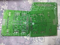
Attachments
Last edited:
How big the heatsink should be for an input voltage around 25-27VAC? Curent threw a fet will be arround 2,5-3A feeding jlh high power amp.
Those look real nice Prasi. They will save a lot of $ in cost of big fat 33mF caps (usually 8) normally needed for a low ripple Class A PSU.
I found the space a bit tight for the 220uF caps but the Panasonic FC's fit okay - can fit other bigger sized ones to the side using slightly longer bent wires - presuming the mounting of the power fets to either a flat heatsink or on the bottom of the case
The sound of the CM-x isn't quite the same as big electro caps, or bunch of little ones, as you know, and much better, IMO.
It does raise a question in my mind about how many of the different brands of caps are actually the same device with just different wrappers on them
A mention of heatsinks - heat dissapation can be quite misleading - if you jlh amp is drawing a continuous 3A (?) plus current peaks, the heat developed across each IRFP fet will be a bit higher than 12w but taking this as a base figure, if you're using a single heatsink for all 4 devices and using good quality insulation washers (suggest Keratherm from this site's store) then the heatsink's going to get rid of 48W into the air around it - if that air gets to about 30*C in summer, you might want to limit the heatsink temp to about 45*C (a temp rise of 15*C) - okay, so far?
So you're looking for a heatsink that has a rating of 15/48 = 0.31 - this is a pretty big heatsink approximately about 300mm long, 150mm high with 40mm fins or you could use a smaller one with a slow fan blowing air across it .
Are you sure the 'jlh' is drawing a continuous 3A from each rail of the power supply/channel or is this the total requirement for both channels of the amp?
If this is so, then the power dissipation is half that described above and the heatsink much smaller at about 0.6*C/W rating.
I don’t know of any Class A amp around here that runs at 3amps. Must be for both channels at 1.5amps each? But 50w is a serious amount of heat. You might be better off with two cap multipliers connected in parallel from same bridges. I have connected parallel Cx’s In parallel to common SMPS and they serve to isolate the two channels from power rail crosstalk. Having two separate ones will physically spread the heat but more importantly gives channel isolation and better ripple control.
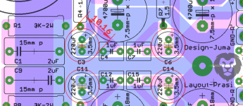
yes, 10mm caps can be fitted albeit a bit tight.
Just a query, can a lower value be used here? e.g. this one, 180uf, panasonic FM
or many like them.
http://in.element14.com/w/c/passive...e=180uf&voltage-rating=50v&lead-spacing=3.5mm
Just a query, can a lower value be used here? e.g. this one, 180uf, panasonic FM
or many like them.
http://in.element14.com/w/c/passive...e=180uf&voltage-rating=50v&lead-spacing=3.5mm
Attachments
I don’t know of any Class A amp around here that runs at 3amps.
Nelson Pass's first DIY amplifier, the Pass A20 published in 1977, is a 20 watt/channel class A design whose DC bias current is 4 amperes in each channel, when set up for 4 ohm loudspeakers. {rated power is 28 watts into 4 ohm load, 20 watts into 8 ohm load}
The Pass article says 220mV across 0r22 for the 4ohms loading and that equates to 3A bias for the single ended 3 BJT output stage.
But that results in Pmax 4ohms = 3A^2 * 4ohms / 2 = 18W into 4ohms ClassA
One would need 4A bias for Pmax 4ohms = 4A^2 * 4 /2 = 32W into 4ohms ClassA
and that needs the Vre to be set to 293mVre
But that results in Pmax 4ohms = 3A^2 * 4ohms / 2 = 18W into 4ohms ClassA
One would need 4A bias for Pmax 4ohms = 4A^2 * 4 /2 = 32W into 4ohms ClassA
and that needs the Vre to be set to 293mVre
Last edited:
Just a shot in the dark. Can the voltage drop be altered by using different value components?
I've built a two-channel Cx based on Juma's schematic and it drops from 24.5VDC (server PSU) to 18.45V. It's for ACA and I was hoping to get 20V, or at the very least 19V.
Btw. I've used IRF610's, not IRFP240. Could that perhaps be the reason for the 6V drop?
This is the circuit I've used:
I've built a two-channel Cx based on Juma's schematic and it drops from 24.5VDC (server PSU) to 18.45V. It's for ACA and I was hoping to get 20V, or at the very least 19V.
Btw. I've used IRF610's, not IRFP240. Could that perhaps be the reason for the 6V drop?
This is the circuit I've used:
Attachments
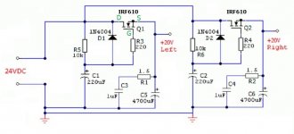
Easiest way to reduce the voltage drop might be, to replace enhancement mode power MOSFET with depletion mode small signal MOSFET (DN2530) and power BJT. Now you can get (Vin - Vout) drop as low as 1.00 volts if you wish. It would be a good idea to also include a 20-turn trimmer pot, so you can accurately "split the difference" between min_Vin (at the trough of the worst case ripple) and min_Vout (required by downstream electronics).
- Home
- Amplifiers
- Power Supplies
- Juma's Easy-Peasy Capacitance Multiplier