Yeah Prasi, that's pretty much how it works - on general terms, there's not much to either grounding point but for some extra higher freq noise, the position where the main gnd is situated is significant.
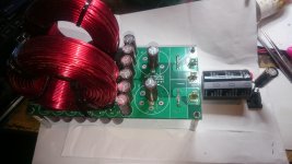
On the cct diagram, the gnd point is drawn adjacent to the power caps, as you originally organized the pcb, but now it can be shown joining the GND +R' and the GND -R' points on the output as the new layout provides - love the neat leds there
Another completed project, eh!
Well done again, or as Hugh says Congratulations - the simple, marvelous C-Multipliers continue to flourish
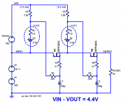
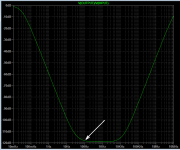
Here's what a cascoded design delivers, using a charge pump to minimize the voltage drops through two series source followers.
TL431 datasheet here
Simulation macromodels of the TL431 are notoriously unreliable so I just modeled it as a 2.5V zener diode whose dynamic resistance is 1 ohm. This is pessimistic compared to the datasheet.
_
TL431 datasheet here
Simulation macromodels of the TL431 are notoriously unreliable so I just modeled it as a 2.5V zener diode whose dynamic resistance is 1 ohm. This is pessimistic compared to the datasheet.
_
Attachments
Last edited:
Here's what a cascoded design delivers, using a charge pump to minimize the voltage drops through two series source followers.
TL431 datasheet here
Simulation macromodels of the TL431 are notoriously unreliable so I just modeled it as a 2.5V zener diode whose dynamic resistance is 1 ohm. This is pessimistic compared to the datasheet.
_
Very good results Mark. But the cascode and the positive gate voltage makes for a little more complex ckt. Do you have a simple charge pump thatll work?
Hi Mark Johnson,
Can you please be more verbose for those of us not familiar with how to build a charge pump? Since you model the LT431 as a Zener and resistor, could we not just use a Zener? Also, I see two stages of cap multiplier being applied here. If we simply took two Juma cap multipliers in series, would the attenuation only improve by -3dB of would it be -45dB x 2 = -90dB. Closer to your -120dB shown here. That is a very impressive figure indeed youth. IRFP240's are cheap - I am game for taking this to the next vias odds charge pumped level if you provide a full schematic without leaving key bits so that "the interested reader can show that..."
Can you please be more verbose for those of us not familiar with how to build a charge pump? Since you model the LT431 as a Zener and resistor, could we not just use a Zener? Also, I see two stages of cap multiplier being applied here. If we simply took two Juma cap multipliers in series, would the attenuation only improve by -3dB of would it be -45dB x 2 = -90dB. Closer to your -120dB shown here. That is a very impressive figure indeed youth. IRFP240's are cheap - I am game for taking this to the next vias odds charge pumped level if you provide a full schematic without leaving key bits so that "the interested reader can show that..."
Could use a joule-thief instead of charge pump. But suddenly we have a complex ckt and might as well build a proper regulator. For me the interest in the C-x is the simplisity. How about designing in the voltage drop by using a transformer with 3-4 volts more out than otherwise?
And yes cascading two after each other does indeed bring the attenuation down to -90dB or more. In the simulator that is. Will be inteesting to compare the real thing.
And yes cascading two after each other does indeed bring the attenuation down to -90dB or more. In the simulator that is. Will be inteesting to compare the real thing.
The simplest way adding a bit headroom voltage is, add a few turns (try 10 turns and measure VAC) of wire wound around the toroid or C core (IE cores may work if there's space to add few turns), one end connected to the supply voltage onto which C-x is connected to, the other side of the wire is connected to anode (cathode for negative voltage) of a single diode (half wave rectifier) and a filter electrolyte, that's it.
Another simple way is using voltage doubler with a string of diodes and capacitors:
Voltage doubler - Wikipedia
The caveat is it's doubling the voltage and may be more than asked for.
All oscillating/switching charge pumps etc. may be prone to both directly and indirectly injecting high frequency noise into our audio circuits and therefore needs a bit of analysis and care in its implementation, so therefore isn't always as straight forward a "easy-peasy" solution.
See following link:
emc - EMI in charge pump switching regulator - Electrical Engineering Stack Exchange
Juma's easy-peasy X-c is elegant for what it is. 🙂
Last edited:
Try it in simulation and find out. Don't forget to measure the DC voltage drop from Vin to Vout, it might be as much as 12 volts. One benefit of the charge pump approach is that if you apply it shrewdly, you can reduce the voltage drop from Vin to Vout quite substantially. Especially if you've chosen high-gm MOSFETs.If we simply took two Juma cap multipliers in series, would the attenuation only improve by -3dB of would it be -45dB x 2 = -90dB.
Other members have commented that there is another DC-to-DC converter circuit besides a charge pump, called a boost-type switch mode power supply using an inductor. This is absolutely correct. However boost-type SMPS circuits sometimes poop out when the load current is very small, as it is here (less than 3mA), so read your datasheets thoroughly and design your circuits carefully.
Happy designing!
Certainly a negative feedback voltage regulator made with discrete components would have stunningly greater attenuation at low frequencies (including 120 Hz), all the way down to DC. (here are some measurements) But it wouldn't be a Capacitance Multiplier and it would have more than 6 total parts.
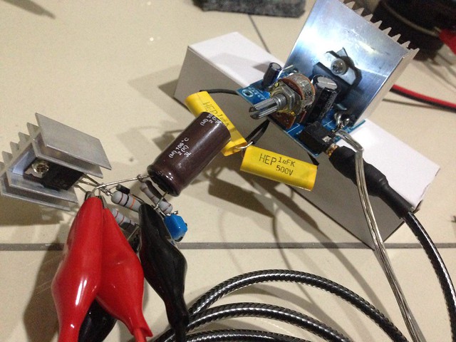
With this heatsink, after playing for 45 minutes, I can only touch the heatsink with my fingertips for 5 seconds. Is it normal or do I need bigger heatsink?
With this heatsink, after playing for 45 minutes, I can only touch the heatsink with my fingertips for 5 seconds. Is it normal or do I need bigger heatsink?
Hi Jonathan,
Try to calculate 4.5 V drop x current to get the heat dissipated in mosfet. In any case I think heatsink is too small.
regards
Prasi
if u can keep ure finger on it for 5sec its not much more than 70C. Which is ok if u do not have it right on to the electrolytic.
How do u think it works? Do u notice less noise? Is it worth it?
How do u think it works? Do u notice less noise? Is it worth it?
OK I think it's reasonable to source a bigger piece.
To be honest I don't notice any less noise, I'm afraid to say there is more noise. My system is already quiet, I really have to press my ears against the driver. This is volume on the amp at full and on the preamp at zero. Now, with the same position, there is more noise, I can even hear the music playing a little bit. Can anyone explain why?
That is the downside, on the plus side, I noticed improvements in the sound. Bigger, fuller sound, at the same time more transparent and clear. Highs are more open and clear. Mids and vocals sound natural and 'immediate'. Those are my impressions after +/- 5 hours listening in total.
Theres a limit to how quiet ampifiesr get. Even if pure DC is fed at the rails, there is current and voltage noise in each component in there. So if the pre- and amplifier's self noise is dominating, even if it is very low, an improved voltage rail will not be noticed.
The loss of voltage and powerdissipation in the C-x is probably just waste.
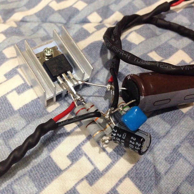
Increased noise with the C-x could perhaps be the new layout/wiredress? More of a crows nest perhaps?
Slight leakeage of sound thru your system even if the volume is all the way down is normal. Few volume pots attenuate infinitely. Also you may hear music via the components inside the amp being slightly microphonic.
The loss of voltage and powerdissipation in the C-x is probably just waste.
Increased noise with the C-x could perhaps be the new layout/wiredress? More of a crows nest perhaps?
Slight leakeage of sound thru your system even if the volume is all the way down is normal. Few volume pots attenuate infinitely. Also you may hear music via the components inside the amp being slightly microphonic.
Okay that's a relief. 🙂
I think my pre amp is pretty well optimized (designed by diyaudio member 'bimo') but I wouldn't be surprised if my power amp is noisy. The chip itself (TDA7297) is not known as being very quiet, and the layout is not very optimized. I didn't notice this leakage prior to installation of C-x, but I can re-check to confirm this. And you do have a point regarding the crow's nest. Thanks for your input, I have some homework to do, it seems.
Not taking away from my point: I still realize an increase in sound quality. 🙂
The cap multiplier may have brought your noise floor down low enough that you are now hearing more leakage intelligibly? So, in fact it may be quieter but it makes smaller details more apparent? One sure way to know is to measure it. If you have a sound card use REW and the RTA and Generator feature to see the noise and distortion.
Here is the Juma Mx sim and a CLC sim. The CLC Filter can be a nice addition as a 2nd stage taking over the Mx right at about 1KHz. The draw back its just more hardware under the chassis.
Pic showing Class A requirements at 22V 3amps.
CLC = Vin 10 x 1000uF > 2.2mH inductor > Vout 10 x 1000uF
Pic showing Class A requirements at 22V 3amps.
CLC = Vin 10 x 1000uF > 2.2mH inductor > Vout 10 x 1000uF
Attachments


Last edited:
Thank you x,
here are the schematic, stuffing guide and gerbers. LED resistors mount from bottom.
regards
Prasi
Thanks again, Prasi. I've received my boards, in both versions, and I look forward to using them.
- Home
- Amplifiers
- Power Supplies
- Juma's Easy-Peasy Capacitance Multiplier