Thanks x, I will refine and use fastons.
Fastons when cleverly spaced and with proper footprint , can also accommodate screw terminal blocks.
I too have come to dislike cheap chinese and local termi blocks, but the ones from TE are simply superb (bucchanan series- 282857-5 TE Connectivity / Buchanan | Mouser India ) and very durable.
24 A /300V and 30AWG to 12AWG.🙂
regards
Prasi
refined... with RN60 resistor footprint, + 2USD easyeda pcb compatible😀
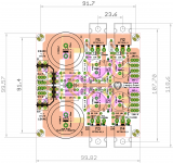
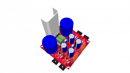
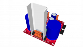
heatsink for power diodes made from aluminium plate bent in shape shown.
regards
Prasi
heatsink for power diodes made from aluminium plate bent in shape shown.
regards
Prasi
Attachments

Last edited:
Thanks, Prasi, I was just about to give in and use a switcher for my Pass M2, but this would work quite well, I'm sure, with the many linear supply parts I have sitting in the basement.
Will you be producing boards yourself, or do we need to supply the board house with the appropriate files?
Will you be producing boards yourself, or do we need to supply the board house with the appropriate files?
Thanks, Prasi, I was just about to give in and use a switcher for my Pass M2, but this would work quite well, I'm sure, with the many linear supply parts I have sitting in the basement.
Will you be producing boards yourself, or do we need to supply the board house with the appropriate files?
Hi tubesguy,
I will post all the gerbers files required for board manufacturing by boardhouses. you could order it yourself. 11 pcbs for 12 USD total @ easyeda.
Let me refine it a bit more, by tomorrow.
regards
Prasi
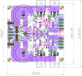
Four cap multipliers on one small PCB.
Well done !
Thanks Andrew.
regards
Prasi
Thanks again, Prasi. Ordered boards this morning. I'm looking forward to getting this project completed.
Yes, thank you Prasi - this is going to be a very useful board to have. Fitting four onto a 100mm square is true art and huge cost savings for us to get fabricated at typical PCB maker where huge discounts for small 100mm exist.

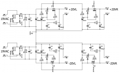
Under Class A operation I am a little concerned about how much heat dissipation we would need on those TO220 diodes. Assuming 1.5amp working current, that's about 1w ea or nearly 8w total for all diodes on the dual bridge. One option is to use an external monolithic bridge (center bolt with 4 spades), in which case we could add some clever jumpers at the appropriate diode holes and connect the DC input to the AC spades. But for Class AB operation, the setup as is will be just fine.
Under Class A operation I am a little concerned about how much heat dissipation we would need on those TO220 diodes. Assuming 1.5amp working current, that's about 1w ea or nearly 8w total for all diodes on the dual bridge. One option is to use an external monolithic bridge (center bolt with 4 spades), in which case we could add some clever jumpers at the appropriate diode holes and connect the DC input to the AC spades. But for Class AB operation, the setup as is will be just fine.
Last edited:
Hello friends, greetings to all. Very nice layout prasi, and interesting discussion throughout the thread.
Sorry to take the discussion down to pre-school level, but I need your help for my project here. I am building a p2p CM for a TDA7297 amp, meaning, stereo and single rail power supply. The schematic on page 1 refers to dual mono dual rail power so I had to extrapolate a little bit.
This far is no problem, but since I am illiterate in schematics, let me confirm a few things:
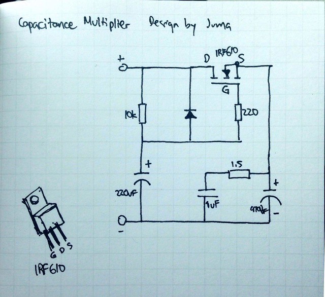
- DC+ from rectifier connects to the 10k resistor (that is in parallel with 1N400*) then connects to Drain in the MOSFET
- DC- from rectifier connects to negative lead of 220uF cap
- Positive lead of 4700uF cap connects to Source in MOSFET, also acting as DC+ output?
- Negative lead of 4700uF cap joins the negative lead of 220uF cap, effectively as common ground so DC- input (from rectifier) and output (to power amp) are also joined in the same spot?
Please advise, before I blow something ^^
Thanks so much, appreciate the handholding.
Sorry to take the discussion down to pre-school level, but I need your help for my project here. I am building a p2p CM for a TDA7297 amp, meaning, stereo and single rail power supply. The schematic on page 1 refers to dual mono dual rail power so I had to extrapolate a little bit.
This far is no problem, but since I am illiterate in schematics, let me confirm a few things:
- DC+ from rectifier connects to the 10k resistor (that is in parallel with 1N400*) then connects to Drain in the MOSFET
- DC- from rectifier connects to negative lead of 220uF cap
- Positive lead of 4700uF cap connects to Source in MOSFET, also acting as DC+ output?
- Negative lead of 4700uF cap joins the negative lead of 220uF cap, effectively as common ground so DC- input (from rectifier) and output (to power amp) are also joined in the same spot?
Please advise, before I blow something ^^
Thanks so much, appreciate the handholding.
Jonathan,
You are 100% correct. That's all there is to it. Just keep in mind that a mosfet like IRF610 will drop about 4v from input to output. So size the upstream PSU appropriately to get desired voltage downstream. An SMT mosfet like ZVN4306 drops only about 3v. An IRFP240 can drop as much as 4.5v.
You are 100% correct. That's all there is to it. Just keep in mind that a mosfet like IRF610 will drop about 4v from input to output. So size the upstream PSU appropriately to get desired voltage downstream. An SMT mosfet like ZVN4306 drops only about 3v. An IRFP240 can drop as much as 4.5v.
Last edited:
Yes, thank you Prasi - this is going to be a very useful board to have. Fitting four onto a 100mm square is true art and huge cost savings for us to get fabricated at typical PCB maker where huge discounts for small 100mm exist.
Under Class A operation I am a little concerned about how much heat dissipation we would need on those TO220 diodes. Assuming 1.5amp working current, that's about 1w ea or nearly 8w total for all diodes on the dual bridge. One option is to use an external monolithic bridge (center bolt with 4 spades), in which case we could add some clever jumpers at the appropriate diode holes and connect the DC input to the AC spades. But for Class AB operation, the setup as is will be just fine.
Apart from the option suggested by you, one more option below.
I have made a provision for a 1mm thick al plate as a heatsink. one could mount a small finned heatsink to that plate on top.
This is a top-notch layout as usual![/QUOTE]
LOL...not really, but it's a good start for me to make some necessary changes in Sprint.😛
Keep up the good work Prasi!!
LOL...not really, but it's a good start for me to make some necessary changes in Sprint.😛
Keep up the good work Prasi!!
Apart from the option suggested by you, one more option below.
I have made a provision for a 1mm thick al plate as a heatsink. one could mount a small finned heatsink to that plate on top.
xrk,
visual of second option. on this aluminium plate, one could mount something like M-C421 Heat Sink Kit Cincon | Mouser India
but this would a bit of diy effort I guess.
looks pretty isnt it?😉, red boards..
ofcourse one would use to-220 diode insulation in between Al plate and diodes.
Attachments
Last edited:
Jwic,
the irf610 is a bit light duty for that cap multiplier feeding a Power Amplifier.
I would recommend irf630 for that duty, but you may get away with a 620.
Even better at very cheap prices are the irf530 and irf520 (100V) versions.
the irf610 is a bit light duty for that cap multiplier feeding a Power Amplifier.
I would recommend irf630 for that duty, but you may get away with a 620.
Even better at very cheap prices are the irf530 and irf520 (100V) versions.
Jwic,
the irf610 is a bit light duty for that cap multiplier feeding a Power Amplifier.
I would recommend irf630 for that duty, but you may get away with a 620.
Even better at very cheap prices are the irf530 and irf520 (100V) versions.
Hi Andrew, thanks for your input. This is for 12VAC 3A trafo powering a simple stereo chip amp. So I guess it is light duty? What parameter in the datasheet do I need to look for when considering MOSFET in this application? Thanks.
The TDA7297 chip amp doesn't draw very much quiescent current, but you may want more for bass transients, although that is supplied by the on-board caps to some extent. IRFP240 is cheap and will give you all the current you need.
Hi Prasi,
I get it now - make aluminum plate taller to dissipate more. That works for me. Altough I will probably use alum L-channel (2 pieces).
Thanks,
X
I get it now - make aluminum plate taller to dissipate more. That works for me. Altough I will probably use alum L-channel (2 pieces).
Thanks,
X
look at the Idmax valueHi Andrew, thanks for your input. This is for 12VAC 3A trafo powering a simple stereo chip amp. So I guess it is light duty? What parameter in the datasheet do I need to look for when considering MOSFET in this application? Thanks.
610 =3.3A, 620 =5.2A, 630 = 9A, 510 =5.6A, 520 =9.2A
These have to be derated depending on the FET temperature. Compare the 100degreesC to the 25degreesC values.
Also look at the Rdson value. Lower equals better multiplier performance.
- Home
- Amplifiers
- Power Supplies
- Juma's Easy-Peasy Capacitance Multiplier