Nazaroo,
I'm a bit of an amateur so I hope my questions aren't annoying. First, The 6L6-6550 topology you outline is that also balanced? It doesn't seem to me that it is. Second, I've been reading up on MU follower in general and it kind of reminds me of the Aikido. I built an Aikido preamp using 6922's. As advertised it didn't sound like tubes or transistors. It sounded different. Very clean and precise but I found it a little sterile. (Might be my vintage Snells or my vintage ears.) Does this design sound like a 'better' tube amp or something different, like the Aikido
I'm a bit of an amateur so I hope my questions aren't annoying. First, The 6L6-6550 topology you outline is that also balanced? It doesn't seem to me that it is. Second, I've been reading up on MU follower in general and it kind of reminds me of the Aikido. I built an Aikido preamp using 6922's. As advertised it didn't sound like tubes or transistors. It sounded different. Very clean and precise but I found it a little sterile. (Might be my vintage Snells or my vintage ears.) Does this design sound like a 'better' tube amp or something different, like the Aikido
That would depend upon what transformer you use.
I suggest using a 10-20 uF or larger cap to avoid bass issues.
I have used various transformers.
I have not built a pair in over 12 years.
I ask the question as a reminder that you're introducing a series resonance within or just below the audio range.
All good fortune,
Chris
Nazaroo,
I'm a bit of an amateur so I hope my questions aren't annoying. First, The 6L6-6550 topology you outline is that also balanced? It doesn't seem to me that it is.
Perhaps this will help:
If you imagine a tightrope walker using a long pole for balance:
The pole serves two purposes. Not only is it held in the center for balance,
but it also provides an almost unmovable object to lean against, tug and pull in various directions.
The pole is deceptively heavy, due to its length.
If the tightrope walker loses his balance a little bit,
he can pull on the pole to straighten up.
Due to equal and opposite reactions,
his muscle pushing on the heavy weight/inertia of the pole,
he rights himself, while the pole only shifts a tiny bit.
This works provided he only pushes lightly, and briefly.
Now only the pole is shifted, and in danger of tilting off.
But the flexible walker can move his body fairly freely,
in counter-balance, correcting the pole again.
The balancing act is a double-action, combining self-correction,
and then pole-correction so that the two as a unit stay centered.
Now a 'balanced' circuit in the sense here has a left and right,
a positive, and a negative mirror-image of the signal.
Each has its own 'side' or half, and signal path through the amp. (similar to but not the same as a 'stereo' signal.)
So, the way I've drawn it, you can see a bilateral symmetry:
You can hold a mirror horizontally along ground, and see that the top half of the circuit is the mirror reflection of the bottom half.
Now back to the pole: Although the pole has to be 'balanced' at the midway point,
there is nothing requiring that either half must be the same weight or balance all the way along.
in fact, such poles are often heavily weighted at the ends,
so that the inner end of each half is UNbalanced,
lighter than the outer-half.
The balance is not in weight distribution along the pole,
but in distribution on each side of the center only.
Now back to the circuit:
In SRPPs (totem pole push-pulls) generally, there is an attempt a 'balance' between
the top half and bottom half of the 'totem pole'.
Half the total voltage is divided across each tube.
This is done merely so that each tube has a roughly equal amount of headroom for a signal in each stage.
The Mu Follower also needs headroom in top and bottom,
but 'balance' between the two is not critical, nor important at all. The two halves are different circuits (one a voltage amplifier, the other a cathode-follower with unity-gain).
So there is no need for 'balance', except that since they are in series the idle-current will be about the same in each.
When we say that my circuit is 'balanced',
we don't mean that each Mu Follower stage is individually balanced (as in 'top' and 'bottom').
We mean that the two sides of a 'balanced signal' dual path are balanced (as in '+ve signal copy' and '-ve signal mirror copy').
This is the same as the tightrope walker's pole being 'balanced',
at the center between each half,
and not balanced at all in weight between the inner ends
and outer ends of each half.
Certainly, when you remove an accustomed layer of noise, distortion, or 'color' from a sound system,Second, I've been reading up on MU follower in general and it kind of reminds me of the Aikido. I built an Aikido preamp using 6922's. As advertised it didn't sound like tubes or transistors. It sounded different. Very clean and precise but I found it a little sterile. (Might be my vintage Snells or my vintage ears.) Does this design sound like a 'better' tube amp or something different, like the Aikido
it suddenly sounds both clearer and as a side-effect more 'sterile'.
Just as a the right hall adds a charming 'reverb' to well-articulated music,
something seems suddenly missing when you take the Jazz quartet outside in a field,
where the sound is 'flat'.
However, the ear quickly adjusts and learns to appreciate the new clearer signal.
It is also an extra 'pleasure', because it relieves a part of the brain from 'processing'
and filtering out the added noise.
You can hear your girlfriend perfectly well on the phone,
but her voice and frequency response are quite shifted and attenuated.
Your brain, knowing what she sounds like in person filters out these effects,
so that your conscious can concentrate on her message.
Clearer is always better in the long run, both for listening and engineering.
If you can remove distortion, you can then always add it back again later,
in just the right amounts for your personal taste.
This is just what is done in studio in adding the warmth of a tube-condenser microphone,
and a plate -reverb to a singer's voice.
You need a clean signal first, then you can control what you are adding in.
Last edited:
Thanks, now I think I understand. So the two traces that come from off the drawing in post 1 that are connected to the control grids of the 6550's are the inputs that are 180 degrees out of phase? And does this amp also use a transformer on the input? If I understand it correctly, both sides conducting constantly, unlike a push pull? So is it a bit like two single ended output stages 180 degrees out from each other? And if that's right for a unbalanced input you would use only two tubes and one side of the circuit?.
Thanks, now I think I understand. So the two traces that come from off the drawing in post 1 that are connected to the control grids of the 6550's are the inputs that are 180 degrees out of phase? And does this amp also use a transformer on the input?
Something like that, but its best to forget that diagram
and move on to the corrected ones.
You are confusing Push-Pull topology with Class-AB operation.If I understand it correctly, both sides conducting constantly, unlike a push pull?
Any Push-Pull topology can be operated A, AB, or B,
with tubes conducting at all times, most of the time, or half the time respectively.
I prefer and recommend Class A, as all Mu-Follower circuits normally operate.
This is correct.So is it a bit like two single ended output stages 180 degrees out from each other? And if that's right for a unbalanced input you would use only two tubes and one side of the circuit?.
You can use one half of my amp for independent stereo SE operation. But you need two Output Transformers and you save having to have an input transformer.
I'll post a circuit diagram.
If you do so, you'll get a bit of that 2nd harmonic tube sweetness in the mix.
You could rig a mode-switch to alter operation in the same amp!
Build one, use it as a stereo SE, then later build another as a monoblock for Push-pull and more wattage.
Keep in mind that the input signal must be only half as large, before clipping,
and the power output will also be halved.
Last edited:
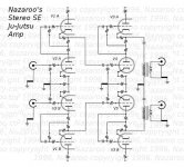
Here's a circuit diagram of the Stereo SE version of my Ju-Jutsu Topology:

The cost difference involves swapping out the input tranny for another output tranny,
and buying one more RCA jack.
The power supply can remain the same.
Now you can all build SE versions at half the cost!
If you like the sound, but want more power, build a second unit.
A 5-tube stereo SE 10 watt amp of unsurpassed purity,
for under $100 plus trannys.
Let the rich cry the blues.
You can listen to their songs with better performance
than they are getting with their $10,000 rigs.
Attachments
Last edited:
Its a Hafler IM distortion adjustment.What is the purpose of common cathode resistors, some kind of stereo base widening?
But in the SE preamp section it can be skipped,
and on the bottom tube I think diodes can be substituted for bias,
but I haven't tried them.
Last edited:
... So is it a bit like two single ended output stages 180 degrees out from each other? And if that's right for a unbalanced input you would use only two tubes and one side of the circuit?.
Sorry, I missed a point here:
SE Output Stage: It won't be only two tubes; For the output, you'll still need some beam tetrodes wired as triodes (they don't come in a two in one envelope).
SE Input Stage: You'll still need two separate tubes, if you're using high voltages (i.e., 500 volts B+) and separate heater supplies.
But you can still halve everything by building it all on one chassis and sharing a single powersupply, and sharing top and bottom tubes (one triode in each for each side Left and Right).
Or you could build the Powersupply on a separate chassis and still share it. It will be more difficult to separate the tubes onto separate chassis, because if you use say a 5998 and share it between channels it will still physically have to be on one chassis or another.
My suggestion is: Rightfully recognize the top tubes as an integral part of the powersupply, with feedback (think of them as fancy Pass-tubes with signal feedback). Mount the top Output tube along with the PS components. It is pretty impervious to hum. The top input tube can also be mounted on the Power-supply, if kept away from other hum-inducing components.
Now your second chassis just contains the lower tubes,
two HV powersupply connections, and only one (lower/grounded) heater supply for the lower tubes (plus a ground). Going backward through the same HV connections (each really coming from the top tubes, not directly from the power supply), the control signal will be applied to the grids of the top tubes on the PS chassis through a cap. These leads should be shielded, but they will only be 200-400 volts, and much safer ran as PS lines to another chassis than a real HV connection (at 500-800 volts).
Being on the PS chassis means you only need one top Input stage tube (dual triode) and one top Output tube (dual triode).
The amp chassis will have one lower input tube (say a 12ax7) and two SE output tubes (say a couple of 6L6s), two trannys, and two RCA input jacks.
A very nice small footprint.
The mode-switching can be accomplished on the amp chassis, with an input tranny mounted and switched in between the RCAs. The second output tranny can also be switched out, leaving a balanced/unbalanced input monoblock.
Now the total number of tubes stays the same: FIVE TUBES, for two channels at 12 watts/channel.
Last edited:
Lets rearrange the Top Tubes in our amp, and put them on a separate Power-Supply Chassis,
with the HV B+.
For SE operation, we have to do a little extra isolating of HV power supply to the top tubes,
using additional Cap/Resistor legs. (top of diagram).

Also, we install the signal caps on the PS chassis, so that at least two of the connecting lines
have no High Voltage DC (this is blocked by the caps.
Even the two lines with DC only have half the full B+ voltage,
since it is divided ('dropped') across the Top Tubes.
You can use ordinary 600 volt insulation wire (shielded) between PS and Amp Chassis.
Make sure you orient any connectors safely (males on receiving circuits, females on power sources).
Although there are now two tubes (a 12AX7 and a 5998 for instance) on the PS chassis,
it really isn't any more than you'd find on almost any regulated HV powersupply.
What has happened is that we have simply made more intelligent use of similar tubes,
with much more spectacular results.
Why have a mere 'regulated' supply, when you can have a 'feedback-controlled' CSS supply?
Don't forget to add a good heavy gauge ground line between the two chassis.
with the HV B+.
For SE operation, we have to do a little extra isolating of HV power supply to the top tubes,
using additional Cap/Resistor legs. (top of diagram).
Also, we install the signal caps on the PS chassis, so that at least two of the connecting lines
have no High Voltage DC (this is blocked by the caps.
Even the two lines with DC only have half the full B+ voltage,
since it is divided ('dropped') across the Top Tubes.
You can use ordinary 600 volt insulation wire (shielded) between PS and Amp Chassis.
Make sure you orient any connectors safely (males on receiving circuits, females on power sources).
Although there are now two tubes (a 12AX7 and a 5998 for instance) on the PS chassis,
it really isn't any more than you'd find on almost any regulated HV powersupply.
What has happened is that we have simply made more intelligent use of similar tubes,
with much more spectacular results.
Why have a mere 'regulated' supply, when you can have a 'feedback-controlled' CSS supply?
Don't forget to add a good heavy gauge ground line between the two chassis.
Attachments

Last edited:
Now we can see the Ju-Jutsu Amp (SE Stereo) in its true light and simplicity.
It is simply a pure two-stage amplifier, in real linear operation,
with a pristine DC supply, and no current in the OT.
Click to enlarge:
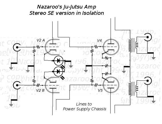
I've stuck in some LEDs to bias the first stage, as some people might want to try it.
When the Mu-Follower is understood as it really is,
a sophisticated power-supply regulator circuit combined with an ideal load,
we can see plainly how the amp achieves near-perfect distortion-free operation.
The only two caps in the signal path are in the PS chassis.
It is simply a pure two-stage amplifier, in real linear operation,
with a pristine DC supply, and no current in the OT.
Click to enlarge:
I've stuck in some LEDs to bias the first stage, as some people might want to try it.
When the Mu-Follower is understood as it really is,
a sophisticated power-supply regulator circuit combined with an ideal load,
we can see plainly how the amp achieves near-perfect distortion-free operation.
The only two caps in the signal path are in the PS chassis.
Attachments
Last edited:
Lets rearrange the Top Tubes in our amp, and put them on a separate Power-Supply Chassis,
with the HV B+.
Nazaroo, I'm not seeing what is the advantage of relocating the upper tubes of the Mu-Follower to the P.S. chasiss. Please clarify. Thanks.
Nazaroo, I'm not seeing what is the advantage of relocating the upper tubes of the Mu-Follower to the P.S. chasiss. Please clarify. Thanks.
(1) It helps isolate the real dangerous high voltage and keep it contained in the powersupply.
(2) Teaching purposes, so that people can understand the true meaning of the Mu-Follower.
(3) The separate heater supply for the top tubes (with HV offset) is also isolated.
The heater supply is perhaps the most dangerous, because even seasoned technicians
forget that it can have lethal HV riding on it.
Last edited:
(1) It helps isolate the real dangerous high voltage and keep it contained in the powersupply.
Okay, yes. If the H.V. supply is to be placed in a separate chassis then locating the upper tubes there will produce a less dangerous interconnection between the two chassis. I was picturing the P.S. and amplifier circuitry in the same chassis, hence my question.😛
It is quite feasable to eliminate even the interstage coupling caps (with careful design and testing),
since with a self-biased output stage, you can have up to 100 volts on the output grids.
In this case you would use a 6922 for the first bottom tube, which can run on lower voltages.
Using SE output transformers (to ground) might also allow dropping the output caps.
This leaves only the caps used by the Top-tubes,
which are really only PS regulator feedback caps.
Now you have a capacitor-free signal path right to the speaker.
In my personal design, I've eliminated caps, transformers, and tubes entirely.
The amp consists of a single silver-plated magical wire.
Last edited:
In my personal design, I've eliminated caps, transformers, and tubes entirely.
The amp consists of a single silver-plated magical wire.
Thank you nazaroo for taking your time and energy to post this thread - I'm finding it a fantastic read and even at my age learning new tricks (I am, after all, an old dog)......🙄
As to the single wire amp - have you tried proper marination in Yak urine and cryo treatment? Is proper orientation to the moon's lunar cycles have any effect on balanced output???? 😀😀😀
All I can say is that the cryo-treatment resulted in
quite a stiff power supply, and allowed me to eliminate the Viagra.


Nazaroo, I'm not seeing what is the advantage of relocating the upper tubes of the Mu-Follower to the P.S. chasiss. Please clarify. Thanks.
Here's another great reason to move the top tubes to the Power Supply.
Tubelab has been granted a special free license to make power supply boards to compliment his simple SE and PP boards, using this design. 😉
Now they can become Ju-Jutsu amps by simply adding the appropriate Power Supply. 😀
Thats if Tubelab decides to do it.

Hi,
First I'd like to thank you 'nazaroo' for charing your ideas. I find this thread very
intresting and the ideas is new to me. It gives me a lot to think about.
One thing that you wrote initially was that EL34 isn't good for HiFi and that made
me wonder, don't you like EL34 or did I misunderstand you?
Thanks again.
Rolf
- Status
- Not open for further replies.
- Home
- Amplifiers
- Tubes / Valves
- Ju-Jutsu: The Ultimate Monoblock